
After installing our first Laser Powder Bed Fusion Additive Manufacturing system, we learned a lot, and while he was at PADT, Dhruv Bhate kindly wrote up a series of blog posts on what we learned.
Here are the articles:
 1")
What equipment does one need for metal 3D printing?
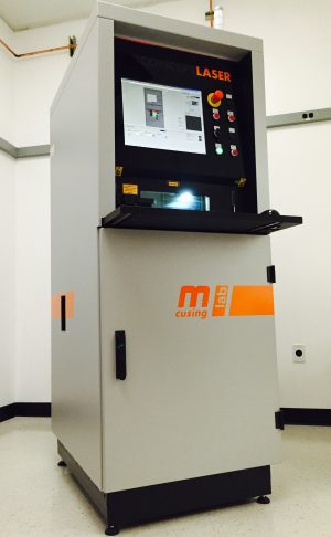
This is the first in a five-part series that brings together the different lessons we learned installing our first metal printer, a Concept Laser MLab Cusing R at PADT, shown in Figure 1. In this post I list the different equipment needed to enable metal 3D printing end-to-end, along with a brief explanation of its purpose. In subsequent posts, I deal with (2) Facilities, (3) Safety, (4) Environmental & (5) Housekeeping aspects of the technology. I hope this information adds to the conversation in a meaningful way and help those who are thinking about, or in the process of installing a metal 3D printer.
The specifics of some of this information will vary depending on the equipment and materials you handle, but my hope is the themes covered here give you a sense of what is involved in installing a metal 3D printer to aid in your preparation for doing the same and for having good discussions with your equipment supplier to ensure these are addressed at a minimum.
One way to look at classifying the equipment needed (beyond the obvious metal 3D printer!) is by its purpose, and I do so here by dividing it into two broad categories: Ancillary Equipment (necessary to the printing itself) and Post-Processing Equipment (focused on the part).
At the outset, it is crucial that the difference between reactive and non-reactive metal alloys be comprehended since a lot of the use of the equipment differs depending on what kind of metal alloy is being used. A previous blog post addressed these differences and these terms will be used in the following sections.
1. Ancillary Equipment
1.1 Wet Separator
 2")
The wet separator is essentially a vacuum cleaner that is designed to safely vacuum stray (“fugitive”) metal powders that cannot be cleaned up any other way. When dealing with powders, the typical recommendation is to first brush whatever you can into the overflow bin so you can reuse it. The next step is to try and wipe up powder with a moist lint-free cloth (to be covered in the housekeeping post). The wet separator has a water column that passivates the metal powder and renders it non-reactive to allow for easier disposal (to be covered in the environmental post). Wet separators require a significant amount of maintenance, particularly when dealing with reactive metals like Titanium and Aluminum alloys, where the supplier recommends the wet separator be cleaned out on a daily basis. At least one company has developed a kit to help with wet separator cleaning – which gives you an indication of how significant of an issue this is. Most suppliers provide a wet separator along with their equipment.
1.2 Glove Box
 3")
A glove box is a useful piece of equipment for dealing with reactive metals in particular. The glove box allows an operator to manage all the powder handling in the build chamber to be done in a closed environment. For non-reactive metals this is not a necessary piece of equipment but it is highly recommended for reactive metals. The glove box when used in concert with reactive metals will allow for inert gas flushing out of oxygen to low PPM levels prior to operator intervention, and also includes grounding connections for the box to the machine. The nice thing about having a glove box is it reduces the amount of time you need to have a respirator on by allowing you to add powder and unpack builds in a closed environment. The glove box may also be integrated into the machine itself – ours is a stand alone device on wheels that we roll over to the machine when we need it.
1.3 Powder Sieve
Unless you plan on disposing all the powder in each build after it is completed, you need a sieve to separate out the larger particles and contaminants from the powder you wish to reuse in subsequent builds. The sieves are also typically provided with the machine and can be enabled with inerting capability (as shown in Fig 4 on the left, or as shown on the right, come as a small desktop unit that can sieve about 3-5 lbs of powder at a time). While the sieve on the left may be used for reactive metal sieving, it is uncertain if one can safely use the desktop sieve for the same, even with grounding the table it sits on and the operator – this is a gray area and I am keen to hear thoughts on this from those that have the expertise/experience in this space.
 4")
1.4 Ultrasonic Cleaner
 5")
The purpose of the ultrasonic cleaner is to remove as much trapped powder as possible before the part and the build plate are subjected to any post-processing – this is to minimize the risk of trapped powder getting airborne during downstream processes – which cannot be completely eliminated (which is why PPE should be used all the way through till the final part is in hand after cleaning).
The Ultrasonic cleaner is used twice: first before the parts are removed from the build plate, and again after they are removed. Sometimes I will even use it a third time after all supports have been removed, if the part has internal p. I typically use the 40 kHz and 60 C temperature setting but have not sought to further optimize the parameters at this time.
2. Post-Processing Equipment
2.1 Furnace
 6")
The purpose of the furnace is to relieve residual stresses built in the parts prior to removing them from the build plate. So this is the first step after the parts and the plate come out of the ultrasonic cleaner. We use a furnace that allows for nitrogen or argon flushing, and place our parts wrapped in stainless steel foil in a gas box. Instructions for heat treatment (time and temperature profile) are typically provided on the technical specifications that come with the material. Metals like stainless steel can be stress relieved in a nitrogen atmosphere but Inconels and Ti6Al4V for example require higher temperatures of between 800-1000 C and argon atmospheres – so you need to be setup for both gases if you are considering running more than 1 metal in your operation.
2.2 Support Removal
All parts are connected to the build plate by between 3-5mm of supports that need to be removed. This is a two step process: the first step involves removing the parts with supports off the build plate, and this is most commonly done with a table saw or a wire EDM. At PADT, we stumbled upon a third way to do this, using an oscillating hand tool and a carbide blade – which works well for small parts (<3″ in X-Y space). It is important to always wear gloves and a supplier recommended (N95 or higher) respirator while removing supports since there could be trapped powder in the supports that was not removed with the Ultrasonic cleaner. The second step is to use hand tools to pry out the supports from the part – this is why it is important to design supports that have weak mechanical connections to the part itself – ideally you can tear them off with hand tools like a perforated sheet of paper [Video below courtesy Bob Baker at PADT, Inc].
2.3 Die Grinder
 7")
A carbide die grinder is then used to grind away the support-model interface – for tiny parts, this can be achieved with a hand file as well for some parts but is easier to do with a die grinder. For large parts, this need can be eliminated by designing in regions that are to be machined later and aligning these regions with supported regions, so as to reduce the need for finishing on these surfaces.
2.4 Face Milling
This may come as a bit of a surprise, but you also need some way of replenishing the build plates after use so you can re-use the plates – this involves using a face milling technique to remove all the remnant supports on the build plate and take off a thin slice at the top of the build plate, while retaining flatness to within 100 microns (0.004″). Having this capability in-house will greatly speed-up your ability to start successive prints and reduce the need to keep large inventories of build plates [Video below courtesy Bob Baker at PADT, Inc].
2.5 Surface Finishing
A combination of techniques can be used for surface finishing. At a minimum, you must have the ability to do glass bead blasting – this is both for the printed parts, but also for the build plate itself – a bead blasted finish is recommended to improve the adhesion of the first layer of powder to the build plate.
 8")
2.6 Other Capabilities
The list above is what I would consider a minimum list of capabilities one needs to get started in metal 3D printing, but is not comprehensive and does not include facility, safety, environmental and housekeeping requirements which I will cover in future posts. Additional CNC equipment for machining metal AM parts, heat treatment and HIP, and superior surface finishing and cleaning techniques are often called upon for metal AM production, but these are highly dependent on application and part design, which is why I have left them out of the above list.
Move on to part 2 of this series where I discuss the facilities requirements for metal 3D printing (electrical, inert gas etc.). Did I miss anything or do you have a better way of doing the things described above? Please send your thoughts to info@padtinc.com, citing this blog post, or connect with me on LinkedIn.
Acknowledgements:
Garrett Garner at Concept Laser, Inc and Bob Baker at PADT, Inc. for their insight and expertise that helped us select and bring in the above capabilities at PADT.
Continue Reading:


