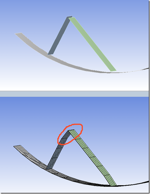
Anyone who has had to mesh shell assemblies has probably run into trouble with edges that don’t quite line up, edges that meet in the middle of faces and other problems that make the meshing process difficult. Often geometry operations were required to reconcile those problems and many times significant effort was required to get a continuous mesh.
Another historically used tool to connect shell assemblies was the use of constraint equations to connect edge nodes to surface nodes on the finite element level. More recently, advances in contact technology have allowed for the use of nonlinear contact elements to connect shell assembly meshes. Both of those techniques, while useful, have some drawbacks. For example, constraint equations do not support large rotations of the geometry as the direction of application does not change as nodes rotate. Also, contact elements increase the computational expense if they can otherwise be eliminated.
ANSYS, Inc. now provides us with another technique for handling shell assembly meshing, called Mesh Connections. First available in version 13.0 and enhanced in version 14.0, mesh connections use the mesher itself to connect shell assemblies toward the goal of getting a continuous or conformal mesh across the surface bodies that make up the assembly.
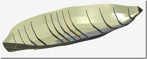
Consider this boat hull example. It consists of panel surfaces defining the hull as well as some stiffening ribs. All geometry is composed of surface bodies.
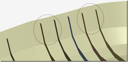
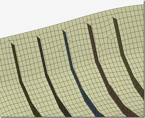
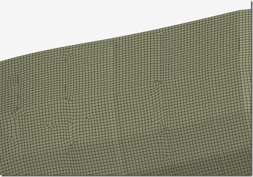
Some of the ribs line up with edges in the hull surfaces, while others do not as shown in the close up image shown below.
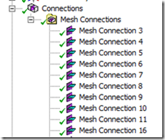
We can now create mesh connections in the Connections branch after loading this geometry into the Mechanical editor in Workbench 14.0.
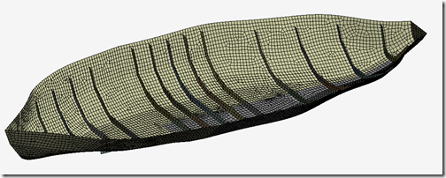
Upon generating the mesh, the mesher will attempt to create a continuous or conformal mesh even though we have do not have intersecting geometry.
With the default settings, we can see in this image that it did a fairly good job of creating the mesh for the ribs which do not intersect with the hull surfaces. Nodes on the hull surface were adjusted so that they connect to the rib geometry.
In this case with relatively little effort we were able to obtain a continuous mesh between the ribs and the hull, even though the several of the ribs shared no intersections with the hull surfaces. In fact, the mesh connections were able to overcome small gaps in between the geometry as well.
In 14.0, the mesh connections are generally performed after the initial mesh is created by default. This means that if changes are made only to mesh connection settings, the remeshing operation is fairly quick since the initial mesh does not need to be regenerated in most cases.
Note that mesh connections exist in the Connections branch, not the Mesh branch. The mesh connection setup works in similar fashion to contact region creation in that searching for edges/faces to connect is based on proximity. The proximity value can be controlled via a slider or by entering an explicit distance, both available in the Mesh Connections details window.
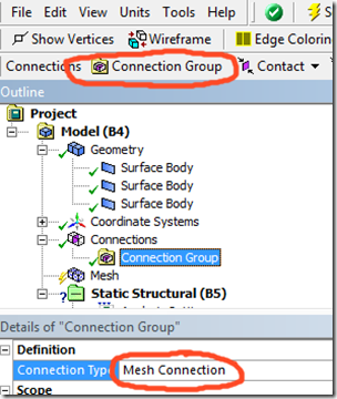
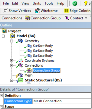
To activate mesh connections, highlight the Connections branch and click on the Connection Group button in the context sensitive menu above the outline tree. Change the Connection Type to Mesh Connection in the details.
Next right click on the Connections branch and select Create Automatic Connections. You may need to adjust the auto detection tolerance in the details to make sure the tolerance distance is large enough to detect desired gaps between edges and faces or edges and edges for the mesh connection to work.
If any contact regions have been automatically created that you want to replace with mesh connections, delete or suppress them. You have the choice of automatically creating mesh connections or manually creating them. Both options are available by right clicking.
In the example shown here, mesh connections are edge to face. Edge to edge mesh connections are also available.
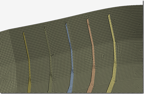
With a couple of mesh settings added, we can obtain a better mesh:
Note that the hull surface nodes have moved a bit in order to allow for the mesh connections with the ribs. Here is a view of the outer hull surface in the mesh connection region:
There are other considerations as well, such as which geometric entities should be the master or slave. In general slave geometry is ‘pinched’ into the master geometry. Also, mesh connections can be setup manually for cases where the auto detection is not appropriate or is not providing the desired level of control. Note that the mesh can end up as an approximation of the geometry since the mesh will have moved to close gaps. Here is an example:
In summary, mesh connections are another tool that are available to us in ANSYS meshing capabilities, having value for shell assemblies. In cases where shell geometry edges do not meet at intersections we can still obtain a continuous mesh without having to perform additional geometry operations. Mesh connections can be faster than using contact elements at the edges as well. There are other features and considerations for mesh connections which are explained in the ANSYS 14.0 Help. We recommend you give them a try if you are tasked with simulating shell type structures.

