When you couple ANSYS Workbench’s automation features, ease of use, and advances in computer resources, it typically results in some rather large models. When I first started using ANSYS, I remember fighting tooth and nail to avoid using contact and keep the model size under 200k nodes. Fast forward to a recent consulting job that included 70 contact regions, 30 kinematic joints, and a total model size around 700k nodes, and I barely batted an eye.
Some problems you run into with models at this size and complexity is figuring out “what am I looking at?”, “what’s connected to this?”, “why is the mesh doing that?”, just to name a few. The brute force way to figure most of these out is to go through each tree item, one at a time, until the part you’re looking at lights up. This is probably okay for a single component or small assembly, anything larger and it becomes a daunting task. Luckily, there’s an easy way around this, simply click the right mouse button (RMB) and select the ‘Go To’ branch. This will fire up the Large Hadron collider and help you find what you’re looking for (sans the risk of singularities and destruction of all mankind).

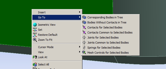
The image shown was taken in R12.1 (note that if you’re still using v11 some of these options are not available…time to upgrade!). While most of these options seem self-explanatory, I get paid for each word I write (just kidding), so here’s a quick summary for all the options shown:
| Corresponding Bodies in Tree | Highlights selected body in geometry branch – allows you to change material properties of selected parts, note that you can have a vertex, line, area, or body selected…either way it’ll bring you to the ‘parent’ body |
| Bodies Without Contacts in Tree | Regardless of what’s currently selected, it will highlight all bodies in the geometry branch that do not have a contact pair – handy for chasing down the ‘max DOF incremenet’ error caused by an unconstrained body |
| Contacts for Selected Bodies | Selects all contacts for the selected body – first place I check when I get odd stress results on my parts, typically because of an ‘accidental’ contact pair |
| Contacts Common to Selected Bodies | Selects only contact pairs between selected parts – Note that you must have >1 part selected or this won’t work, nice way of figuring out how two parts are connected |
| Joints for Selected Bodies | Similiar to ‘Contacts for Selected’, only with kinematic joints |
| Joints Common to Selected Bodies | Similiar to ‘Contacts Common to…’, only with kinematic joints – again a very nice feature to figure out how two parts are connected |
| Springs for Selected Bodies | Similiar to the ‘Contacts for…’ or ‘Joints for…’, only you guessed it, will show user-defined springs that attach to the body |
| Mesh Controls for Selected Bodies | Shows all mesh controls for the body currently selected – nice for answering the question “why is the mesh doing that?” type of issues |
As noted in the description list, it does not matter what part of the body you have selected when you use the ‘Go To’ feature. You can have a vertex, line, area, or the entire body highlighted. ANSYS Mechanical understands what your selection belongs to, and takes you to the appropriate item. So let’s say you have 5 different components that you need to change the material properties for. Highlight a face on each body, RMB > Go To > Corresponding Bodies in Tree, then make the material change in the Details Window. The change will be applied to all selected bodies.
The ‘Go To’ functionality is also available within ANSYS DesignModeler, the CAD creation/simplification/modification/etc moduls within Workbench.

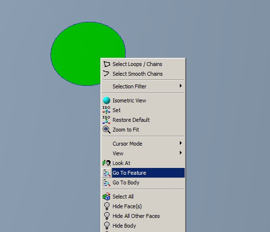
Within DesignModeler, you have two options:
| Go To Feature | Takes you to where the selected feature (vertex, line, area, body) was created, handy in finding out where a surface patch or ‘stranded’ line was created |
| Go To Body | Takes you to the body within the parts-list at the bottom of the tree window, helpful in assigning thicknesses to surface bodies or renaming parts |
As noted above, I use the ‘Go To Feature’ to identify where surface patches or stranded lines (line imprinted through part of an area) come from. Depending on the body status (active or frozen) and the filtering used for certain operations, you can accidentally create imprints in unintended regions (the new ‘Projection’ tool, available in R12, is a big help in preventing this because it doesn’t ‘care’ if a body is active or frozen).
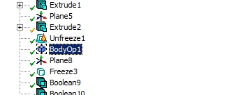
Using the picture above, if I wanted to figure out where that circular area came from, I would select it > RMB > Go To Feature and it would highlight this operation in the model tree:

In the Details Window I would see that this Body Operation was set to ‘Imprint Faces’.
So, to summarize, there is no need to go blind and suffer from carpal tunnel when trying to find out details of your model. Just remember the ‘Go To’ function!
As a side note, I realize that the likelihood of the LHC producing a black hole capable of destroying the universe is extremely small. Any black holes that could be generated would be short lived, and require so little negative mass to neutralize that we need not worry.


