FE Modeler Part 3: Morphing Meshes

Categories:

Morph-lady-catIn the first two parts of this series we talked about how to use FE Modeler to translate meshes and how to create geometry from meshes.  The third “big” thing that this tool does is allow you to morph a mesh to a new shape.  There are a few less important things that FE Modeler does, and we will cover those in the last article of this series.

First, let’s take a good long look at the picture to the left.  Mesh morphing is nothing like what the image shows, but it is pretty creepy to look at so I thought I’d throw it up there.

Mesh morphing in FE Modeler works by taking the faceted surface geometry you can create, covered in the previous article, and allowing the user to apply transformations or a projection to that geometry.  You would use this if you want to change your geometry while keeping the same basic mesh.  This is because when you are doing optimization or parametric study and changing the CAD geometry, you force a remesh every time and sometimes the change in mesh is large enough to effect your study.  You would also need to use this method if all you had was an FE mesh.

Basic Process

Let’s start with a very simple example to show how it is done. 

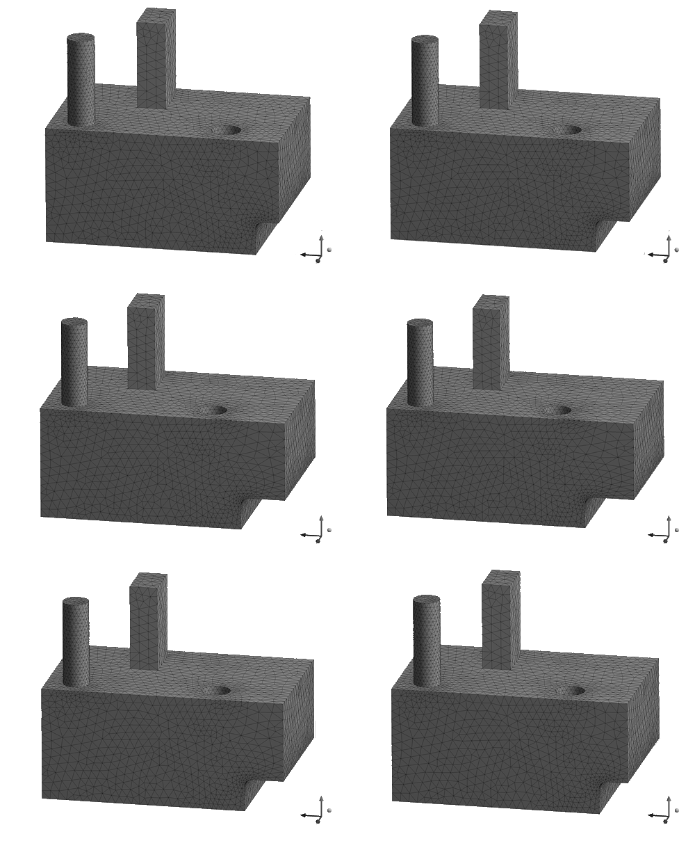
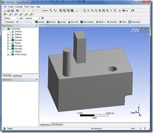
Figure 1 shows a piece of example geometry.  It has some nice features that we will do more complex morphs on.
f1_geometry
Figure 1: Simple Example Geometry, Itching to be Morphed

To start off we do the same geometry (covered in detail in Part 2 of this series):

  1. Read in geometry
  2. Select Geometry Synthesis in the tree and make sure Use Node components is Yes
  3. Click on the Initial Geometry Icon
  4. If everything works you should have a solid that you can now work with

Now you need to define how you want to modify the faceted geometry.  Do this by selecting Initial Geometry in the tree and then clicking on the “New Target Configuration” Icon.  See Figure 2.
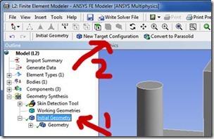
 

f2_MakeTargetConfigurationFigure 2: Creating the Target Configuration

When you do this the program will go out and configure some things internally and then add two new things to the tree: 1) a “Target Configuration” that is a child of Initial Geometry and 2) a Parameterized configuration branch. Figure 3 shows the result in the tree.
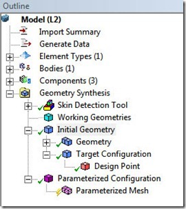
 

f3_Tree_After_Target_ConfigFigure 3: Model Tree After Creation of Target Configuration

So, at this point you might be trying to figure out why there are branches and children where they are. The way I think about it is that the Geometry Synthesis listing is not a branch and is not a child of something.  It is it’s own “tree”  So everything on the first level under it, its children, are different things you can do with Geometry Synthesis:  Find skins, define working Geometry,  Set up mesh Morphing (Initial Geometry), and view what the current mesh looks like based on the current parameters (Parameterized Configuration).  I feel that the Initial Geometry branch is mislabeled and should say Mesh Morphing, but it is too late to change the name now.

Back to morphing meshes…  The way you specify what you want morphed is to define Design Points that have some sort of translation or projection.  Then you specify how far to translate with a parameter that you control in the Project Schematic.  For our first run through, we are going to offset a surface. 

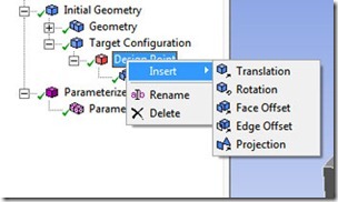
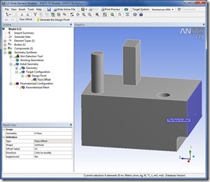
Do this by clicking on Design Point and then on the Transformation Icon and Select “Face Offset” (or RMB –>Insert->Face Offset) and fill out the details view.  For this example I used the end face and set the maximum offset value to 30 mm.  Note, even though it doesn’t say it in the GUI, the help points out that you should put in your maximum value that you might use.  the program then scales from the original to this value as you change the offset parameter.  Figure 4 shows the setup for this example.
f4_Offset_face
Figure 4: Specifying the Face Offset, Before Generation

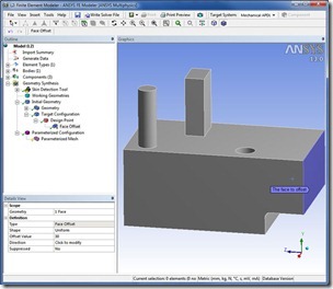
Click on Generate the Design Point to see what the offset looks like:
f5_Offset_Face_2
Figure 5: The Offset Face after Generation

Here is where it gets a little tricky.  All you did was define a potential geometry change.  That change is not applied to the model until you actually set parameters and apply them.   And, the parameter is controlled at the Project Schematic level, not within FE Modeler.  The value you put in under Design Point, that is simply a maximum value that the program uses to figure out how to do the Morphing.  The actual morphing uses the parameter as defined in the Project Schematic.

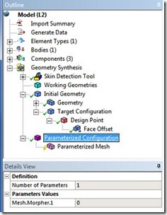
To see this click on Parameterized Configuration and you will see that there is 1 parameter, it is called Mesh.Morpher.1, and its value is 0.  (Figure 6).
f6_ParamValues
Figure 6: Configuration Information after Offset is Defined

Therefore, your next step is to go to the project schematic and change the offset value to some new value you want to morph the mesh to (remember, the value we put in for the Design Point is our guess at the maximum value, we can use any value we want for the parameter value).  To change the value in the Project Schematic, bring up the schematic and click on the parameter bar.  You should now see the parameter in the Outline view. For this example, I changed it to 17.354.  Now exit back to the parameter manager and click on Update Project.  Go back to your FE Modeler window, click on Parameterized Mesh, and you should see the morphed mesh:

f7_morphed_mesh
Figure 7: Morphed Mesh

Figure 8 shows an animation from an offset of 0 to 30: 

SimpleMorph1

Figure 8: Mesh Morphing from an Offset of 0mm to 30mm

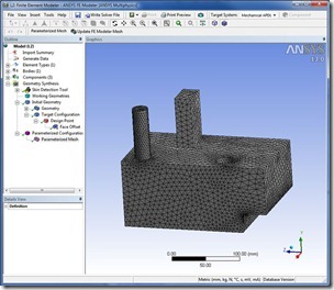
To get the mesh out and usable in your model you have one more step.  If you click on Write Solver File now you will get your original geometry.  You need to click on Parameterized Mesh then click on the Update FE Modeler Mesh icon.  Now set your Target System and chose Write Solver file.  Or, if you are staying in workbench, drag a new system onto the Model in the Project Schematic.  The cool thing about this is that you now have a parametric model that is linked to an analysis in Workbench. It is therefore easy to do design studies, optimization, and the rest of the cool things Workbench is great at, and without CAD geometry!  Figure 9 shows an example of using the mesh for a modal analysis.
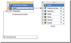
f9_Use_Morphed_MeshFigure 9: Using the Morphed Mesh in a Modal Analysis

Getting More Complicated

Although the process is the same, you can get a lot more complicated.  The program allows for five different translations, offsets or projections, and some of them have multiple options within. They are all kind of self explanatory.

  f10_tranlation_options
Figure 10: Morphing Options

Here is the description from the help as a reference:

  • Translation (of vertices, edges, surfaces, or parts): A translation is given in the global Cartesian coordinate system or by the definition of a translation vector between two points.
  • Rotation (of vertices, edges, surfaces, or parts): You must define a rotation axis between two points or a point and a vector and then give a rotation angle in degrees or radians.
  • Face (Surface) Offset – a Face Offset can be:
    • Uniform – Enter a negative or positive Offset Value to move the face inward or outward.
    • Non Uniform – Enter a negative or positive Offset Value to move the face inward or outward. With this transformation, you can offset a surface with a nonlinear curve. In addition, a Non Uniform surface offset includes the following options:
      • Distance to the edges – Define the distance from the edges to the maximum displacement of the transformed face.
      • Function type – Select a function type based on the shape you want to obtain, options include: Linear, Double Tangent, Linear-tangent, Tangent-linear.
      • Immobile edges – By default, all of the edges for the target surface are selected. You can de-select edges if desired.
  • Edge Offset: An offset of one edge along a face by a specified distance; always with a given sign depending on the edge normal.
  • Projection: a projection of a face, an edge, or a vertex onto a face, edge, or vertex or a group of faces or a group of edges. The Projection transformation works in tandem with the Working Geometries feature. Using an imported Working Geometry, you can project the entities of a Target Configuration onto the entities of the imported (Working) geometry.

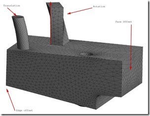
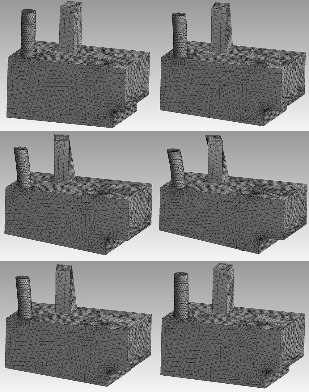
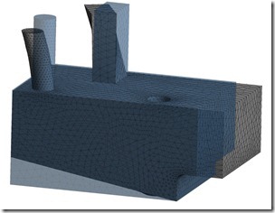
For this example I added a rotation for the block sticking up, a translation for the top circle face of the cylinder, and an edge offset for the lower right edge.  the result is shown in Figure 11. 
 f11_Morphed-Unmorphed
Figure 11: Part with Offset, Rotation, Translation and Edge Offset Applied. Overlaid on Original Mesh

f12_Morphed_With_labels

Figure 12: Part with Offset, Rotation, Translation and Edge Offset Applied. Labeled. 

Mesh_Morph2

Figure 13: Animation of Morphing

Whew, that is a lot of material, and we are out of time to get this article back.  Look for a Part 3.5 in the near future filling in some missing pieces and a few more examples.

If you want to try this yourself, ask you sales professional for  temp Key of the ANSYS Mesh Morpher. And as always, start simple and work your way to more complex parts.

Categories

Get Your Ansys Products & Support from the Engineers who Contribute to this Blog.

Technical Expertise to Enable your Additive Manufacturing Success.

PADT’s Pulse Newsletter

Keep up to date on what is going on at PADT by subscribing to our newsletter.


By submitting this form, you are consenting to receive marketing emails from: . You can revoke your consent to receive emails at any time by using the SafeUnsubscribe® link, found at the bottom of every email. Emails are serviced by Constant Contact

Share this post:

Upcoming Events

09/27/2023

2023 AZ Bio Awards

09/26/2023

Experience Stratasys Truck Tour - Houston

09/22/2023

AIAA Rocky Mountain Section Technical Symposium 2023

09/22/2023

Experience Stratasys Truck Tour - Dallas, TX

09/21/2023

Accelerating the Energy Transition through Simulation

09/20/2023

3D Printing vs. CNC Machining - Webinar

09/13/2023

Maxwell Updates in Ansys 2023 R2 - Webinar

09/12/2023

Sandia Science & Technology Park 25th Anniversary

09/12/2023

Experience Stratasys Truck Tour - Tempe, AZ

09/08/2023

26th Annual New Mexico Flying 40 Awards

09/08/2023

New Mexico Tech Summit

09/07/2023

New Mexico Tech Summit

08/30/2023

Structures Updates in Ansys 2023 R2 (1) - Mechanical, Post & Graphics

08/23/2023

Improved Injection Molding with Additive - Webinar

08/22/2023

SPIE Optics & Photonics Exhibition 2023

08/16/2023

Fluids Updates in Ansys 2023 R2 - Webinar

08/04/2023

Experience Stratasys Truck Tour - Salt Lake City, Utah

08/01/2023

Experience Stratasys Truck Tour - Denver Colorado

07/26/2023

Solving Supply Chain Issues with Additive - Webinar

07/25/2023

Arizona Tech Leadership Golf Tournament

07/24/2023

Arizona Tech CEO Leadership Retreat

07/19/2023

System Automation & Optimization Updates in Ansys 2023 R1 - Webinar

07/13/2023

2023 AEROSPACE, AVIATION, DEFENSE AND MANUFACTURING CONFERENCE

07/12/2023

Materials Updates in Ansys Granta 2023 R1 - Webinar

06/30/2023

Turbo Expo 2023

06/29/2023

Turbo Expo 2023

06/28/2023

Turbo Expo 2023

06/28/2023

Revolutionize Packaging Design with Additive - Webinar

06/27/2023

Turbo Expo 2023

06/27/2023

2023 E-MOBILITY AND CLEAN ENERGY SUMMIT

06/26/2023

Turbo Expo 2023

06/21/2023

Optics Updates in Ansys 2023 R1 - Webinar

06/07/2023

LS-DYNA Updates in Ansys 2023 R1 - Webinar

05/31/2023

Driving Automotive Innovation with Additive - Webinar

05/24/2023

Hill Air Force Base Tech Expo

05/24/2023

Structural Updates in Ansys 2023 R1 (3) – Structural Optimization & Ex

05/23/2023

CROSSTALK 2023: Emerging Opportunities for Advanced Manufacturing Smal

05/10/2023

Signal & Power Integrity Updates in Ansys 2023 R1 - Webinar

04/26/2023

Additive Manufacturing Updates in Ansys 2023 R1 - Webinar

04/20/2023

38th Space Symposium Arizona Space Industry

More Info

04/19/2023

38th Space Symposium
Arizona Space Industry

04/19/2023

Additive Aids for Manufacturing - Webinar

04/18/2023

38th Space Symposium
Arizona Space Industry

04/17/2023

38th Space Symposium

04/13/2023

Venture Madness 2023

04/12/2023

Fluid Meshing & GPU-Solver Updates in Ansys 2023 R1 - Webinar

03/29/2023

8th Thermal and Fluids Engineering Conference

03/29/2023

Structural Updates in Ansys 2023 R1 - Composites, Fracture & MAPDL

03/28/2023

8th Thermal and Fluids Engineering Conference

03/27/2023

8th Thermal and Fluids Engineering Conference

03/26/2023

8TH Thermal and Fluids Engineering Conference

03/24/2023

Arizona BioPreneur Conference | Spring 2023

03/22/2023

2023 Arizona MedTech Conference

03/22/2023

Optimize Jigs & Fixtures with Additive - Webinar

03/15/2023

3D Design Updates in Ansys 2023 R1 - Webinar

03/08/2023

Competitive Advantages of 1D/3D Coupled Simulation - Webinar

03/01/2023

High Frequency Updates in Ansys 2023 R1 - Webinar

02/22/2023

Additive Advantages in Aerospace - Webinar

02/15/2023

Structural Updates in Ansys 2023 R1 (1) - Webinar

02/09/2023

IME 2023: MD&M | WestPack | ATX | D&M | Plastek

02/08/2023

IME 2023 MD&M | WestPack | ATX | D&M | Plastek

02/07/2023

IME 2023 MD&M | WestPack | ATX | D&M | Plastek

01/27/2023

Arizona Photonics Days, 2023

01/26/2023

Arizona Photonics Days, 2023

01/26/2023

TIPE 3D Printing | 2023

01/26/2023

Venture Cafe Phoenix Talent Night - Job Fari

01/26/2023

VFS 2023 Autonomous/Electric VTOL Symposium

01/25/2023

Arizona Photonics Days, 2023

01/25/2023

Building A.M.- Utah: Kickoff!

01/25/2023

TIPE 3D Printing | 2023

01/25/2023

VFS 2023 Autonomous/Electric VTOL Symposium

01/24/2023

VFS 2023 Autonomous/Electric VTOL Symposium

01/24/2023

TIPE 3D Printing | 2023

01/18/2023

2023 AZ Tech Council Golf Tournament

12/21/2022

Simulation Best Practices for 5G Technology - Webinar

12/14/2022

Digital Twins Updates in Ansys 2022 R2 - Webinar

12/08/2022

Tech the Halls - AZ Tech Council Holiday Mixer

12/07/2022

Electric Vehicle and Other Infrastructure Update Panel

11/30/2022

SPEOS Updates in Ansys 2022 R2 - Webinar

11/23/2022

Simulation Best Practices for Electronics Reliability - Webinar

11/16/2022

Discovery Updates in Ansys 2022 R2

11/10/2022

VentureCafe Phoenix Panel: Venture Capital in AZ

11/08/2022

2022 GOVERNOR’S CELEBRATION OF INNOVATION AWARDS + TECH SHOWCASE

11/03/2022

VentureCafe Phoenix Panel: Angel Investment in AZ

11/02/2022

High & Low Frequency Electromagnetics Updates in Ansys 2022 R2

10/26/2022

Simulation Best Practices For Chip-Package-System Design & Development

10/20/2022

Nerdtoberfest 2022

10/19/2022

2022 Southern Arizona Tech + Business Expo

10/19/2022

LS-DYNA Updates in Ansys 2022 R2 - Webinar

10/17/2022

Experience Stratasys Truck Tour - Clearfield Utah

10/14/2022

ASU School of Manufacturing Systems and Networks - Formal Opening Cele

10/14/2022

Experience Stratasys Truck Tour - Midvale Utah

10/12/2022

Experience Stratasys Truck Tour - Littleton Colorado

10/06/2022

Fluids Updates in Ansys 2022 R2 - Webinar

10/05/2022

Experience Stratasys Truck Tour - Colorado Springs

09/29/2022

White Hat Life Science Investor Conference - 2022

09/28/2022

2022 AZBio Awards

09/28/2022

Simulation Best Practices for Rotating Machinery Design & Development

09/21/2022

ExperienceIT NM 2022

Search in PADT site

Contact Us

Most of our customers receive their support over the phone or via email. Customers who are close by can also set up a face-to-face appointment with one of our engineers.

For most locations, simply contact us: