Where we Left Off Last Time…
In the last post of this series, I left you with an introduction to the Microsoft Visual Studio debugger and a description of how to debug scripts that we write. In this post, I’m going to illustrate how to write what might actually turn out to be a useful script! The idea for this script came from a request from one of our users, Craig Hildreth, who has always wished that there was a better way to define slice planes in Mechanical.
Problem Description
Lets say you want to create a slice plane in ANSYS Mechanical that cuts precisely through a certain location in your model and that is precisely oriented to be normal to a certain direction. How would you do it? If you’ve used the slice tool in Mechanical before, you know that you basically yank a line segment with the mouse across the screen. The resulting slice plane is defined such that if you were to extend the line segment you created with the mouse to infinity and then extrude the line in the direction of the current view the resulting plane formed by this operation would be the slice plane. Can it be more intuitive? So, of you go spinning and panning your model around to where you think you are looking right down the slice plane, then with the steadiness of a surgeon you try with all your might to draw a straight line with the mouse. (Good luck!) Now, to ANSYS’ credit, this is a really cool tool if you just want to whip a quick slice plane on the model to look inside somewhere. Especially when you’ve got that cool little drag widget. However, if you are trying to use the slice tool for any kind of meaningful post processing, your probably out of luck. What would be awfully darn useful would be create or use a Cartesian coordinate system that would then define the slice plane. That sounds kind of intuitive, right? Anyway, you might optimistically think that functionality should already be there, but alas to my knowledge it is not. So lets see if we can fake it. (If you just want the code and don’t care how we write it, check out this post where we give the code. This is a long post because it turns out this is trickier than it looks…)
How the Heck Do You Create a Slice Plane… Programmatically that is?
So, step one is to figure out what Mechanical does under the hood when we create a slice plane. If you haven’t read Part 2of this series, I suggest you do so now. We’re going to use the techniques in that post to figure out what Mechanical is doing when we create a slice plane.
Searching the ANSYS Source Files for Info on Creating a Slice Plane
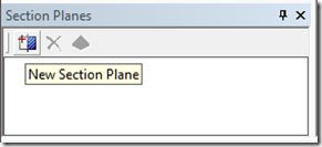
If you haven’t started up Mechanical, do so now and make sure that the slice plane window is visible by ensuring that menu item View->Windows->Section Planes has a check mark beside it. In the section plane window, hover your mouse of the create section plane button. You should see a tool tip like the following:
We see that the tooltip is called “New Section Plane”. This is a string for which we can search. So, search the entire directory tree C:\Program Files\ANSYS Inc\v130\aisol\DesignSpace\ for the string “New Section Plane”. We see that in C:\Program Files\ANSYS Inc\v130\aisol\DesignSpace\DSPages\Language\en-us\xml\dsstringtable.xml we find that string. Remember that this is where you are normally going to find GUI related strings. This string has the string id: ID_NewSectionPlane. So, lets search for that. One place we find this string is inside the file: C:\Program Files\ANSYS Inc\v130\aisol\DesignSpace\DSPages\scripts\DSSectionPlanesScript.js This file name sounds promising. Here is some code from that file showing where the id shows up.
btnAdd = toolbar.Buttons.AddButton( TBT_BUTTON,
"NewSectionPlane", ID_ADD,
"NewSectionPlane", false, "",
localString("ID_NewSectionPlane") );

btnAdd.OnClick.AddCOM(g_sectionPaneObjects,
"SectionPane_Add");
This code is reformatted to fit better in the blog. You can see that the code appears to be adding a button to a toolbar and also registering a callback for when the button is clicked. The callback is what we’re interested in, so lets search for “SectionPane_Add”. Searching for that leads us to the following code:
this.SectionPane_Add = function sectionPane_Add(sender, args)
{
    if (!AllowSlicing ())  return;
    doAddSectionPlane();
 }
We’re getting closer! It looks like we need to peek into doAddSectionPlane(). Let’s search for that. It turns out that that function is a bit of a dead end, but lucky for us right below it we see the following code:
function doDeleteSectionPlane()
{
    var sliceTool  = ds.Graphics.SliceTool;
    if (sliceTool == null)
        return;
   ...
}
Hey! There is something called a SliceTool that is a member of the Graphics object associated with the global DesignSpace Object. Lets quit grepping and slogging through the ANSYS Mechanical code base and fire up the debugger to see what we can learn about the SliceTool.
Using the Visual Studio Debugger to Learn About the Slice Tool
Now that we’ve figured out that there is an object called SliceTool that is a member of the Graphics object, lets use the debugger to interrogate that object. Create the following javascript code and save it somewhere on your hard drive.
function slice_tool_interrogate() {
    debugger;
    var slice_tool = DS.Graphics.SliceTool;
    // Useless code to give us a place
    // to stop
    var i = 1;
}

slice_tool_interrogate();
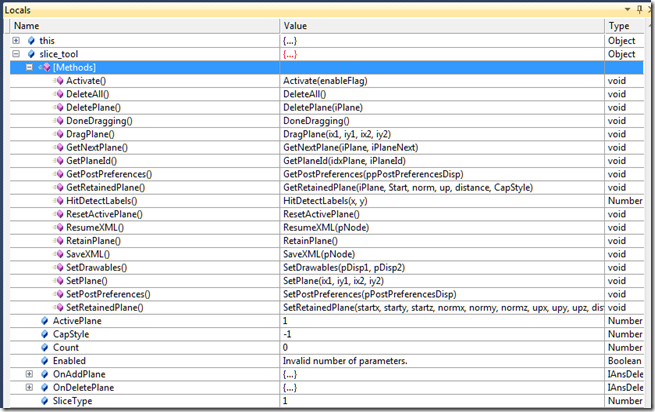
The code above will allow us to stop in the debugger and look at the slice tool object. The following screen shot shows the slice_tool object’s properties and methods in the debugger.
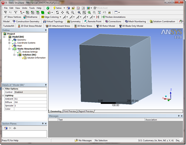
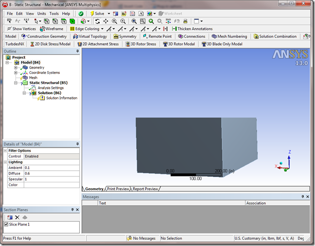
Hmm… Well, there is one function there called SetPlane(ix1, iy1, ix2, iy2) that looks kind of promising. Unfortunately, I don’t see any function that would seem to hint at defining the plane with a point and normal, for example. It looks like the programmatic interface mimics the user interface. Arg… So, lets just guess that given two points in screen coordinates (x1, y1 and x2,y2) we can create a slice plane programmatically. What should x1, y1 and x2, y2 be? Are screen coordinates normalized? Where is the screen origin; top left or bottom right or middle of the screen? The fact that the arguments have an “I” in front of them hints that perhaps they are integers, which would rule out normalized values. What to do? Well, lets try this. Lets orient some geometry so that it is mostly centered with the screen and, using the immediate window in the debugger, pass in some values to see what happens. Here is a screen shot prior to using the immediate window to test things out.
Now, I’m going to run our little test script again under the debugger, but after the slice_tool object is created, I’m going to enter the following into the debugger’s immediate window:
slice_tool.SetPlane(0,0.5,1,0.5)
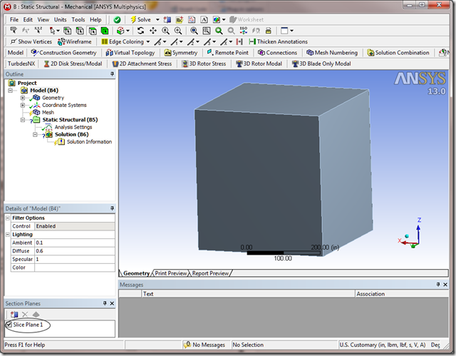
When I do that, I get the following:
So, we created a slice plane!!! Unfortunately, it doesn’t appear that it cut through anything. We learned a couple of things.
- The function DS.Graphics.SliceTool.SetPlane(x1, y1, x2, y2) will indeed create a slice plane object.
- The coordinates don’t appear to be normalized. (Can’t rule this out definitively, but lets try something else.)
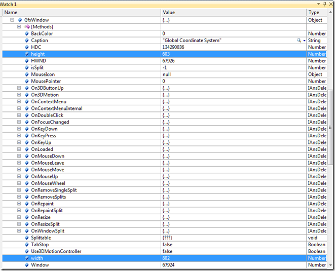
Delete this plane, and lets work with the hypothesis that we need to pass in the screen coordinates as integer values. If I were a programmer, I would choose pixels as my unit of measure for screen coordinates. Things like mouse clicks in particular can be directly translated easily. So, now the question is how big is the screen? Or more precisely, how big is the graphics window? This DS.Graphics object might hold the answers. If you poke around this object inside the debugger you’ll notice that it has a property called GfxWindow. That sounds promising! If we look inside that object, we see:
Ah ha! This thing has a height and a width property associated with it, which I assume by the values associated with these properties are in units of pixels. So lets try the following code. You can modify your little test script as follows:
function slice_tool_interrogate() {
    debugger;
    var slice_tool = DS.Graphics.SliceTool;
    var height = DS.Graphics.GfxWindow.height;
    var width = DS.Graphics.GfxWindow.width;
    var slice_plane =
        slice_tool.SetPlane(0, height / 2, width, height / 2);
    // Useless code to give us a place
    // to stop
    var i = 1;
}
slice_tool_interrogate();
When I run this little script. My “after photo” looks like:
Ha! We got ourselves a genuine slice plane. And, we got it where we want it. Well, sort of… OK, so forgive me for celebrating a minor victory, but we were able to create a slice plane and draw a perfectly straight line right across the middle of the screen. Now, if only we could programmatically rotate and pan the model around so that we are centered right on the origin of the plane we are interested in and we are looking right down parallel to the plane. If we can do that, then we just draw a quick line with the SetPlane function and voila, we’re done.
How the Heck to You Rotate and Pan the View… Programmatically that is?
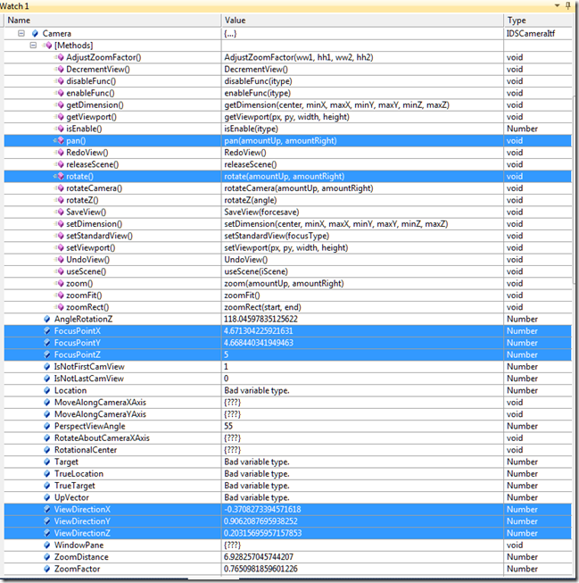
You know, this Graphics object is pretty handy. Lets see what other goodies it might hold. If we poke around in it a bit, we see that it has a property called Camera. Camera sounds like something that would help us look at things from a certain point of view. Here is a peek into the camera object inside the debugger:
This is looking promising. You’ll notice that we’ve got a pan and rotate function. And, it looks like we’ve got a focus point and view direction vector. This is looking good. Maybe we can write a function that will pan the view around until the origin of our coordinate system is centered where we want it and simultaneously rotate the view around until our view direction is oriented how we want it. One other thing we’ll have to figure out is that we could rotate the view about the view direction vector so that it spins around the axis we are looking down. Think of a drill bit spinning. In that case neither the view direction or the focus point would likely change, but there is that rotateZ() function that might bail us out. Lets see if we can figure out what all these things do/mean. Lets start with the following test functions:
function do_pan(up, right) {
    var camera = DS.Graphics.Camera;
    var graphics = DS.Graphics;
    var a = 0;
    for (var i = 0; i < 50; i++) {
        camera.pan(up, right);
        // Just spin her so that the "animation" is more smooth.
        for (var j = 0; j < 1000; j++) {
            a += Math.sin(j);
        }
        graphics.Refresh();
    }
    // I don't know if Javascript does dead code removal, but
    // try to trick any optimizations the javascript interpreter
    // might do to our busy loop.
    return a;
}

function do_rotate(up, right) {
    var camera = DS.Graphics.Camera;
    var graphics = DS.Graphics;
    var a = 0;
    for (var i = 0; i < 50; i++) {
        camera.rotate(up, right);
        // Just spin her so that the "animation" is more smooth.
        for (var j = 0; j < 1000; j++) {
            a += Math.sin(j);
        }
        graphics.Refresh();
    }
    // I don't know if Javascript does dead code removal, but
    // try to trick any optimizations the javascript interpreter
    // might do to our busy loop.
    return a;
}
These two functions basically call the Camera pan and rotate functions repeatedly with some values passed in. Note that if you include these in your little test script, once you stop in the debugger, you can call these functions inside the immediate window and watch what happens. Just type do_pan(5,0) for example. If you play around with these functions, you’ll realize that the rotate function seems to rotate the model about either the screen vertical axis or the screen horizontal axis. Interestingly, the pan function seems to be backwards. That is, the amountUp argument seems to move the model to the right and the amountRight argument seems to move the model up. Ah well… We’ll just make note of it. How do we make sense of all these things?
Math, Math… Wonderful Math! Vectors and Rotations Galore!
Note, if math makes your head spin, we’re going to spin. We’re going to take dot products and cross products and do all kinds of other gyrations. So, feel free to skip this section if you are not interested. However, this section constitutes the meat of figuring out what Mechanical is doing with the graphics given the few bits of information we have highlighted above.
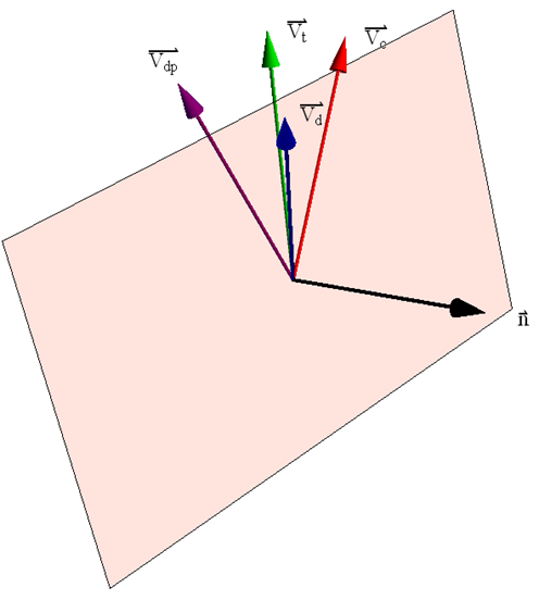
Lets start with rotating the view so that we’re looking where we want to look. Our rotate function spins the model about the screen vertical and horizontal axes, so I’m going to propose an iterative technique that will sequentially rotate up and rotate right until the view vector is parallel to a supplied orientation vector. Remember that we need to look edge on to the plane we wish to use as a cut plane so that we can draw a straight line across our screen and create the cut plane. So, our view vector needs to be “in the plane” of our cut plane. Consider the image below:
The red vector represents the current view direction vector. Now, assume that we call the rotate function associated with the camera object and request an up rotation of 15 degrees. The resulting new view direction vector is represented by the green vector above. Lets call this the test vector. Taking the cross product of these two vectors (green and red) allows us to determine the normal vector, shown in black above, that represents an axis about which our requested rotation occurred. We now know that if we call the rotate function with a value for the up rotation given the current view vector, we will rotate about the normal vector above. So, now rotate the view back to the original view direction. Let’s assume that our desired view direction is show above as the blue vector. In general, it will not be in the plane of our current rotation. However, if we project this vector onto the plane defined by the normal vector and the origin we obtain the purple vector above. Now I know that I can rotate the view in the “up” direction by some angle and get to the purple vector. Its not the blue vector that I want, but it is the projection of the view vector on the plane in which my rotations are occurring. I can calculate a good guess for this angle by taking the ratio of the angle between the green and red vector with respect to my original trial rotation of 15 degrees. Then, if I take the angle between the purple vector and the red vector, divide by my ratio, I’ll get a good guess as to what I should try to rotate my view so that I get to the purple vector. If it works according to plan, this will get me closer to my desired view direction. Now, I repeat this whole process by rotating in the other direction, that is rotating to the right. Between each of these update rotations, I check to see if my current view vector is parallel to my desired view vector within some small tolerance. If things go well, I should walk my way around to the desired view vector. Consider the code below.
// Calculate the dot product of two vectors
function dot(va, vb) {
    return va[0] * vb[0] + va[1] * vb[1] + va[2] * vb[2];
}

// Calculate the length of a vector
function norm(va) {
    return Math.sqrt(va[0] * va[0] + va[1] * va[1] + va[2] * va[2]);
}

// Normalize a vector
function normalize(va) {
    var len = norm(va);
    if (len != 0.0) {
        return [va[0] / len, va[1] / len, va[2] / len];
    }
}

// Calculate the cross product of two vectors
function cross(va, vb) {
    return [va[1] * vb[2] - va[2] * vb[1],
            va[2] * vb[0] - va[0] * vb[2],
            va[0] * vb[1] - va[1] * vb[0]];
}

// Scale a vector by a scalar
function scale(va, sc) {
    return [va[0] * sc, va[1] * sc, va[2] * sc];
}

// Add two vectors
function add(va, vb) {
    return [va[0] + vb[0],
            va[1] + vb[1],
            va[2] + vb[2]];
}

// Subtract vector b from vector a
function sub(va, vb) {
    return [va[0] - vb[0],
            va[1] - vb[1],
            va[2] - vb[2]];
}

function are_parallel(va, vb, tol) {
    return 1.0 - (Math.abs(dot(va, vb)) / (norm(va) * norm(vb))) < tol ? true : false;
}

function are_perpendicular(va, vb, tol) {
    return (Math.abs(dot(va, vb)) / (norm(va) * norm(vb))) < tol ? true : false;
}

// Rotate the view around so that we are looking in the
// direction of the desired view
function rotate_view(desired_view) {
    // Get the camera and graphics objects
    var camera = DS.Graphics.Camera;
    var graphics = DS.Graphics;
    // This is our tolerance for being parallel to the desired view
    var eps = 1e-7;
    // This is the maximum number of iterations we'll try.
    // While loops with a tolerance check only scare me...
    var max_iter = 200;
    // Get the current view
    var view_c = normalize([camera.ViewDirectionX,
                            camera.ViewDirectionY,
                            camera.ViewDirectionZ]);
    // Make sure we're normalized
    dvd = normalize(desired_view);
    // This should be close to 1 if parallel.

    var cnt = 1;
    var b_first_arg = true;
    var normal = null;
    var trial = null;
    var view_p = null;
    var trial_ang = 15;
    var applied_rotation = null;
    var previous_up = 0;
    var previous_right = 0;
    var right_factor = up_factor = -1.0;
    // Loop until we're parallel, or we give up trying
    do {
        var factor = cnt / max_iter;
        factor *= factor;
        factor *= factor;
        // Get the view direction
        vd = normalize([camera.ViewDirectionX,
                        camera.ViewDirectionY,
                        camera.ViewDirectionZ]);
        // Get the current up vector
        camera.rotate(trial_ang, 0);
        trial = normalize([camera.ViewDirectionX,
                       camera.ViewDirectionY,
                       camera.ViewDirectionZ]);
        current_up = normalize(cross(trial, vd));
        // Rotate back so we don't lose our place
        camera.rotate(-trial_ang, 0);


        vd = normalize([camera.ViewDirectionX,
                        camera.ViewDirectionY,
                        camera.ViewDirectionZ]);

        if (b_first_arg) {
            camera.rotate(trial_ang, 0);
        } else {
            camera.rotate(0, trial_ang);
        }
        trial = normalize([camera.ViewDirectionX,
                           camera.ViewDirectionY,
                           camera.ViewDirectionZ]);
        n = normalize(cross(vd, trial));
        // Rotate back
        if (b_first_arg) {
            camera.rotate(-trial_ang, 0);
        } else {
            camera.rotate(0, -trial_ang);
        }
        vd = normalize([camera.ViewDirectionX,
                        camera.ViewDirectionY,
                        camera.ViewDirectionZ]);
        // Only do this rotation if our desired view vector
        // is not nearly parallel to our current axis of rotation
        // If it is, then the code inside the if statement will
        // be skipped.
        if (!are_parallel(dvd, n, eps)) {
            // Project the desired view vector onto our plane of rotation
            vp = normalize(cross(n, normalize(cross(dvd, n))));
            // Calculate the angle between the projected vector
            // and our current view direction
            dot_product = dot(vp, vd);
            needed_rotation = Math.acos(dot(vp, vd)) * 180 / Math.PI

            // Knock it down by a factor associated with our iteration
            // scheme.  This helps prevent spurious jittering as we
            // make our way there.
            needed_rotation *= (1.0 - factor);
            if (b_first_arg) {
                // If we start to diverge, try rotating back the other way
                if(previous_up < needed_rotation) {
                    up_factor = (up_factor < 0.0) ? 1.0 : -1.0;
                    previous_up = needed_rotation;
                }
                camera.rotate(up_factor * needed_rotation, 0.0);


            } else {
                if (previous_right < needed_rotation) {
                    right_factor = (right_factor < 0.0) ? 1.0 : -1.0;
                    previous_right = needed_rotation;
                }
                camera.rotate(0.0, right_factor * needed_rotation);
            }
        }
        // See if we are there yet
        vd = normalize([camera.ViewDirectionX,
                        camera.ViewDirectionY,
                        camera.ViewDirectionZ]);
        b_rotate_converged = are_parallel(vd, dvd, eps);
        if (b_rotate_converged) break;
        // Flip directions
        b_first_arg = !b_first_arg;
//        DS.Graphics.Refresh();
    } while (cnt++ < max_iter);

}
You can try this function out with some test vectors to see if indeed it rotates the view into the desired orientation. One thing you will notice, however, is that the view sometimes is spun at a funny angle as we look down this axis. So all we’ve done is ensured that the camera is pointing in a certain direction, but there still is one degree of freedom, so to speak, left unspecified with the camera. That is, you could spin the camera any way you want around this view direction and still technically be looking down the view direction. So, now how do we figure out what “spin” has been applied to the camera? Moreover, what spin do we want applied?
The answer for the second question above is related to the coordinate system that will define our cut plane. Lets assume that we are wanting to look down the Y axis of the coordinate system which will define our cutting plane, and we want the Z axis of this coordinate system to be pointing straight up on the screen. If we do this, when we draw a straight cut line horizontally across the middle of the screen, we will be defining a cut plane in the XY plane of the specified coordinate system. That is exactly what we want. In the code above we’ve got the part that will enable us to look down the Y axis, now we just need to figure out how to make the Z axis point straight up
In most computer graphics implementations, there is this notion of an “Up Vector” which is defined to be perpendicular to the line of sight and is used to determine “which way is up”. That is, the up vector points in the positive Y axis on the screen. If you look back up at the screen shot for the camera object displayed in the debugger, you will indeed see that there is an UpVector as a member of that object! Yippee!!! Unfortunately, it says “Bad Variable Type”. Bummer. That’s code for “this variable exists but you can’t access it in the scripting language”. We do have this variable, AngleRotationZ, that looks promising, but what is the reference for measuring this angle? Also, we have a function called rotateZ(), which again looks promising, but how are we going to know how much to rotate? We need to know which way is up, and how much to rotate around the camera’s Z axis so that we can orient our view such that when we draw a straight line across the middle of the screen, we’re cutting the model exactly on our desired plane.
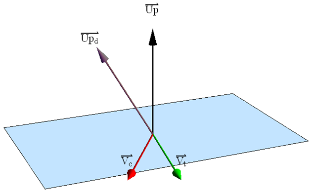
Remember that the first argument to the function camera.rotate(amountUp, amountRight) will rotate the view about the Up Vector. Consider the image below:
Lets assume that we start with our current view direction vector, which is represented in the image above by the red vector. Next, we perform a trial rotation of 15 degrees about the unknown up vector using the camera.rotate(15,0). This moves our view direction vector the green vector shown above. By taking the cross product of these two vectors, we can determine which way is “up” in the world coordinate system. We then rotate the view back to where we started. Now that we know what the current up vector is, we can take the dot product with the desired up vector, shown in purple above, and determine the angle about the camera Z axis we need to rotate so that up is truly up. Not that this assumes that the desired up vector is perpendicular to the current view direction. Consider the code below.
function rotate_up(desired_up_vector) {

    // Get the camera and graphics objects
    var camera = DS.Graphics.Camera;
    var graphics = DS.Graphics;
    var view_c = null;
    var trial = null;
    var current_up = null;
    var theta = null;
    var trial_ang = 15;
    var theta1;
    var theta2;
    var eps = 0.01;
    // Make sure our passed in value is normalized
    duv = normalize(desired_up_vector);

    // Which way are we currently looking now?
    vd = normalize([camera.ViewDirectionX,
                    camera.ViewDirectionY,
                    camera.ViewDirectionZ]);

    // Perform our trial rotation about the screen vertical axis
    camera.rotate(trial_ang, 0);
    trial = normalize([camera.ViewDirectionX,
                       camera.ViewDirectionY,
                       camera.ViewDirectionZ]);
    up = normalize(cross(trial, vd));
    // Rotate back so we don't lose our place
    camera.rotate(-trial_ang, 0);
    // How much to we need to rotate?
    theta1 = Math.acos(dot(duv, up)) * 180 / Math.PI;
    // Rotate assuming a positive rotation
    camera.rotateZ(theta1);
    DS.Graphics.Refresh();
    // Now we need to test to see if this is indeed the proper direction
    // Which way are we currently looking now?
    vd = normalize([camera.ViewDirectionX,
                    camera.ViewDirectionY,
                    camera.ViewDirectionZ]);
    // Perform our trial rotation about the screen vertical axis
    camera.rotate(trial_ang, 0);
    trial = normalize([camera.ViewDirectionX,
                       camera.ViewDirectionY,
                       camera.ViewDirectionZ]);
    up = normalize(cross(trial, vd));
    // Rotate back so we don't lose our place
    camera.rotate(-trial_ang, 0);
    // How much to we need to rotate?
    theta2 = Math.acos(dot(duv, up)) * 180 / Math.PI;
    if (theta2 > theta1) {
        // Rotate backwards if our second guess is larger than our first
        camera.rotateZ(-theta2);
//        DS.Graphics.Refresh();
    }
}
In this code we implement the algorithm sketched out above. The only little trick is that we might end up rotating in the wrong direction. We can determine this by peforming the same test again, and if we are still off then we can rotate back the other direction.
Now that we can look in a particular direction and we can deduce which was is up, all that is left is to pan the view around so that the location of our cut plane is right in the center of the screen. This amounts to figuring out how much to pan in the up and right directions.
If you play with the camera.pan() function you will notice that it appears to use screen coordinates as its arguments. This makes sense from a GUI interface standpoint in that when the user pans the view, they typically do so with the mouse and therefore start and end screen coordinates of a mouse movement are the most natural inputs to a pan routine. Unfortunately for us, that makes panning more of a challenge for us. Nonetheless, lets approach the problem from an iterative viewpoint similar to what we did with the rotations.
We’re going to attach the panning problem using a similar approach as we used for the rotate view function. That is, we’re going to start with a trial pan in one of the directions, look to see what that does in world coordinates, then perform a real pan in that direction, or its direct opposite, to try to get closer to our target. In a similar fashion to the rotate code, we project the pan direction vector in world coordinates onto a plane defined by our current view vector. At each iteration we test the vector from our focus point to the desired point to see if it is parallel to the view vector. If it is, then that means our desired point lies right down the axis of the view vector passing through the focus point. Thus, it would be in the center of the screen. The following code implements this technique.
function pan_view(desired_point) {
    // Get the camera and graphics objects
    var camera = DS.Graphics.Camera;
    var graphics = DS.Graphics;
    // Maximum amount to pan by
    var height = DS.Graphics.GfxWindow.height;
    var width = DS.Graphics.GfxWindow.width;
    // The current focus point
    var fp = null;
    // The trial focus point
    var fp_trial = null;
    // The trial amount to pan
    var trial_pan = (height + width) / 40;  //Unit is pixels...
    // View direction
    var view_v = null;
    // Vector from the focus point to the desired point
    var fp_to_dp = null;
    // Vector of pan direction
    var pan_dir = null;
    // The amount we are going to pan
    var pan_amount = null;
    // Tolerance for determining if the view vector is parallel
    // to the focus point to desired point vector
    var eps = 1e-4;
    // We'll flip back and forth between panning up and panning right
    var b_first_arg = true;
    // The current count of our iteration
    var cnt = 0;
    // The maximum number of iterations to perform
    var max_iter = 200;

    var look_at = desired_point;
    var max_pan = (height + width) / 20;
    do {
        fp = [camera.FocusPointX,
              camera.FocusPointY,
              camera.FocusPointZ];
        vd = normalize([camera.ViewDirectionX,
                        camera.ViewDirectionY,
                        camera.ViewDirectionZ]);

        if (b_first_arg == true) {
            camera.pan(trial_pan, 0);
        } else {
            camera.pan(0, trial_pan);
        }
        trial = [camera.FocusPointX,
                 camera.FocusPointY,
                 camera.FocusPointZ];
        // In world coordinates, see which direction this pan took us
        pd = sub(trial, fp);
        // Project this onto a plane defined by the current view
        // vector
        pd_in_view = cross(vd, cross(pd, vd));

        // Move back to our original location
        if (b_first_arg == true) {
            camera.pan(-trial_pan, 0);
        } else {
            camera.pan(0, -trial_pan);
        }
        fp = [camera.FocusPointX,
              camera.FocusPointY,
              camera.FocusPointZ];
        // Take a vector from the current focus point to the
        // desired center point
        fp_to_dp = normalize(sub(look_at, fp));
        // Only try to pan the view if the vector between our focus
        // point and view vector are not parallel.
        if (Math.abs(1.0 - Math.abs(dot(fp_to_dp, vd))) > eps) {
            // Project this onto a plane defined by the view direction
            fp_to_dp_in_view = cross(vd, cross(fp_to_dp, vd));

            // Normalize the pan test vector so we can walk our way there
            pd_in_view = normalize(pd_in_view);

            // Figure out how much we need to pan

            pan_amount = trial_pan * dot(fp_to_dp_in_view, pd_in_view);
            // Knock it down by a factor associated with our iteration
            // scheme.  This helps prevent spurious jittering as we
            // make our way there.
            var factor = cnt / max_iter;
            pan_amount *= (1.0 - factor * factor * factor);

            if (b_first_arg == true) {
                camera.pan(pan_amount, 0);
            } else {
                camera.pan(0, pan_amount);
            }
            b_pan_converged = false;
        } else {
            b_pan_converged = true;
        }
        // Flip the direction
        b_first_arg = !b_first_arg;
//        graphics.Refresh();
    } while (cnt++ < max_iter && !b_pan_converged);
}
If you’ve hung with me this far, you know that we’ve got a function that will rotate our view so that we’re looking down a particular axis. We’ve also got a function that will rotate the view about our line of sight so that we can make sure a particular direction is up. Finally, we’ve got a function that will pan the view around so that a particular point in space shows up right in the middle of the screen. All of this was accomplished with the limited set of functions and properties we could deduce from the Camera object using the debugger. We also demonstrated how to create a slice plane using the technique of “drawing” al line straight across the middle of the screen. With these four functions we should have all we need conceptually to create a slice plane right where we want it, oriented exactly as we want it.
Implementation
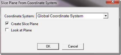
The following code implements these ideas and creates a little dialog box that is presented to the user. I’ll cover the implementation of a dialog box in a separate post, however, you may be able to decode the secret sauce here anyway. The user interface works as follows. You pick a coordinate system from the drop down list for which you would like to create a slice plane. You can then either create a slice plane from this coordinate system, or have the code automatically reorient the view so that you are looking down the Z axis of this coordinate system. Below is a screen shot of the dialog box that is presented, and finally, a listing of the entire code for the script.
Listing of the Code
Here is a listing of the entire script.
// This string contains the HTML code for the dialog box
// we will present to the user
var html_text =
'<html xmlns="http://www.w3.org/1999/xhtml" >\n'+
'<head>\n'+
'<title>Slice Plane Creation Tool</title>\n'+
'<style type="text/css">\n'+
'    body\n'+
'    {\n'+
'        background: buttonface;\n'+
'        font: messagebox;\n'+
'    }\n'+
'    table\n'+
'    {\n'+
'        border-collapse:collapse;\n'+
'        font: messagebox;\n'+
'    }\n'+
'    select\n'+
'    {\n'+
'        margin: 2px 8px 2px 4px;\n'+
'        width: 250px;    \n'+
'        height: 28px;\n'+
'    }\n'+
'    input\n'+
'    {\n'+
'        margin: 0px 4px 0px 0px;\n'+
'    }\n'+
'</style>\n'+
'<script type="text/javascript">\n'+
'    var wb, xfer;\n'+
'    function window_onload() {\n'+
'        xfer = window.external;\n'+
'        wb = xfer("wb");\n'+
'        var cs_group = xfer(\'csys_group\');\n'+
'        var cs_select = xfer(\'csys_select\');\n'+
'        if (cs_group != null) {\n'+
'            populate_coordinate_systems(cs_group, cs_select);\n'+
'        }\n'+
'    }\n'+
'    function window_onunload() {\n'+
'        xfer("CSYS") = parseInt(csys_select.value);\n'+
'        xfer("CreateSlicePlane") = create_plane.checked;\n'+
'        xfer("ViewPlane") = view_plane.checked;\n'+
'    }\n'+
'    function populate_coordinate_systems(cs_group, cs_select) {\n'+
'        csys_select.options.length=0;\n'+
'        for (var i = 1; i <= cs_group.Children.Count; i++) {\n'+
'            var csys = cs_group.Children.Item(i);\n'+
'            var csys_name = csys.Name;\n'+
'            var csys_id = csys.ID;\n'+
'            if (csys_id == cs_select) {\n'+
'                csys_select.options[i - 1] = new Option(csys_name, csys_id, true, true);\n'+
'            } else {\n'+
'                csys_select.options[i - 1] = new Option(csys_name, csys_id, false, false);\n'+
'            }\n'+
'        }\n'+
'    }\n'+
'</script>\n'+
'</head>\n'+
'<body onload="window_onload()" onunload="window_onunload()" scroll="no">\n'+
'<table>\n'+
'<tr>\n'+
'<td>\n'+
'<table>\n'+
'<tr>\n'+
'<td nowrap="true">Coordinate System: </td>\n'+
'<td><select id="csys_select"></select></td>\n'+
'</tr>\n'+
'</table>\n'+
'</td>\n'+
'</tr>\n'+
'<tr>\n'+
'<td>\n'+
'<input id="create_plane" type="checkbox" checked="checked" />Create Slice Plane\n'+
'</td>\n'+
'</tr>\n'+
'<tr>\n'+
'<td>\n'+
'<input id="view_plane" type="checkbox"  />Look at Plane\n'+
'</td>\n'+
'</tr>\n'+
'</table>\n'+
'</body>\n'+
'</html>\n';


var SC = DS.Script;

// Entry point for the whole script.
function main() {

    // Create the dialog
    var slice_plane_dialog =
        SC.CreateActiveXObject(
            SC.GenWBProgId('WBControls.WBHTMLDialog')
            );
    var dlg_OK = 1;
    var dlg_Cancel = 2;
    var dlg_VScroll = 4;
    var flags = dlg_OK | dlg_Cancel | dlg_VScroll;
    var caption = 'Slice Plane From Coordinate System';
    var width = 410;
    var height = 110;
    var b_modal = false;
    // Create the html code from a temporary file
    var fso = SC.fso;
    var tfolder = fso.GetSpecialFolder(2);
    var tname = fso.GetTempName();
    var tfile = tfolder.CreateTextFile(tname, true);
    tfile.WriteLine(html_text);
    tfile.Close();
    var path = fso.BuildPath(tfolder.Path, tname);
    var xfer =
        SC.CreateActiveXObject(
            SC.GenWBProgId('WBControls.DlgArgs')
            );

    xfer('wb') = WB;
    xfer('dlg') = slice_plane_dialog;
    var csys_group = get_coordinate_system_group();

    if(csys_group == null) {
        SC.WBScript.Out('Cannot find the coordinate system group in the tree.' +
                        ' Please create a coordinate system first', true);
        return;
    }
    // Pass over to the dialog the coordinate system group.
    xfer('csys_group') = csys_group;
    var active_obj = DS.Tree.FirstActiveObject;
    if (active_obj.Class == SC.id_CoordinateSystem) {
        xfer('csys_select') = active_obj.ID;
    } else {
        xfer('csys_select') = -1;
    }
    // Show the dialog
    var ret = slice_plane_dialog.DoDialog(WB.hWnd,
                                          path,
                                          xfer,
                                          b_modal,
                                          width,
                                          height,
                                          flags,
                                          caption);
    if (ret == 1) {
        // We get here if the user presses OK on the dialog,
        // so lets grab the user's choices back from the selection.
        var selected_csys = xfer('CSYS');
        var create_plane = xfer('CreateSlicePlane');
        var look_at= xfer('ViewPlane');
        // Do the work here
        var origin = get_coordinate_system_origin(selected_csys);
        var z_axis = get_coordinate_system_z_axis(selected_csys);
        var y_axis = get_coordinate_system_y_axis(selected_csys);
        // Bail out if we can't create the vectors for the coordinate system
        if (origin == null || z_axis == null || y_axis == null) {
            SC.WBScript.Out('Cannot determine the coordinate system vectors.' +
                            ' Unable to create slice plane', true);
            return;
        }
        if (create_plane == true) {
            create_slice_plane(origin, z_axis, y_axis);
        }
        if (look_at == true) {
            look_at_plane(origin, z_axis, y_axis);
        }
    }

    // Delete the html file to clean up
    fso.DeleteFile(path);
}

// Very simple utility function that is used to write out an html
// file to another file in javascript string format.  This is useful
// for pasting into a source file to package the html file into
// a single source script for distribution purposes.
function write_html(path) {
    var fso = SC.fso;
    var input = fso.OpenTextFile(path, 1, false);
    var output = fso.CreateTextFile(path + '.out', true);

    while (!input.AtEndOfStream) {
        var line = input.ReadLine();
        output.WriteLine('\'' + line + '\\' + 'n\'+');

    }
    output.WriteLine('\'\';');
    output.Close();
    input.Close();
}

// Return the origin of a given coordinate system
function get_coordinate_system_origin(csys_id) {
    var csys = get_coordinate_system(csys_id);
    if (csys == null) {
        return null;
    }
    return [csys.OriginXLocation,
            csys.OriginYLocation,
            csys.OriginZLocation];
}

// Return a vector oriented along the z axis of a given
// coordinate system
function get_coordinate_system_z_axis(csys_id) {
    var csys = get_coordinate_system(csys_id);
    if (csys == null) {
        return null;
    }
    return normalize([csys.ZDirectionXValue,
                      csys.ZDirectionYValue,
                      csys.ZDirectionZValue]);
}

// Return a vector oriented along the y axis of a given
// coordinate system
function get_coordinate_system_y_axis(csys_id) {
    var csys = get_coordinate_system(csys_id);
    if (csys == null) {
        return null;
    }
    return normalize([csys.YDirectionXValue,
                      csys.YDirectionYValue,
                      csys.YDirectionZValue]);
}

// Return an actual coordinate system object given
// a tree ID.
function get_coordinate_system(csys_id) {
    var group = get_coordinate_system_group();
    if (group == null) {
        return null;
    }
    for (var i = 1; i <= group.Children.Count; i++) {
        var child = group.Children.Item(i);
        if (child.ID == csys_id) {
            return child;
        }
    }
    return null;
}

// Return the coordinate system group in the tree.
function get_coordinate_system_group() {
    var branch = SC.getActiveBranch();
    if (branch == null) {
        return null;
    }
    return branch.CoordinateSystemGroup;
}

// Create a slice plane given a point, plane normal and up
// vector.  This function uses the orientation functions
// below
function create_slice_plane(point, plane_normal, inplane_up) {
    // Get a handle to the slicetool
    var slice_tool = DS.Graphics.SliceTool;

    // Orient the view using our view orientation functions
    for (var i = 0; i < 3; i++) {
        rotate_view(inplane_up);
        pan_view(point);
        rotate_up(plane_normal);
        DS.Graphics.Refresh();
    }

    // Get the window's dimensions
    var height = DS.Graphics.GfxWindow.height;
    var width = DS.Graphics.GfxWindow.width;

    // Create the slice plane
    var slice_plane =
        slice_tool.SetPlane(0, height / 2, width, height / 2);
    DS.Graphics.Refresh();
}

// Look at a particular point along an axis.  This is useful
// for looking at a slice plane after it has been created.
function look_at_plane(point, normal, up) {
    // Orient the view using our view orientation functions

    // Orient the view using our view orientation functions
    for (var i = 0; i < 3; i++) {
        rotate_view(normal);
        pan_view(point);
        rotate_up(up);
        DS.Graphics.Refresh();
    }

}

// Calculate the dot product of two vectors
function dot(va, vb) {
    return va[0] * vb[0] + va[1] * vb[1] + va[2] * vb[2];
}

// Calculate the length of a vector
function norm(va) {
    return Math.sqrt(va[0] * va[0] + va[1] * va[1] + va[2] * va[2]);
}

// Normalize a vector
function normalize(va) {
    var len = norm(va);
    if (len != 0.0) {
        return [va[0] / len, va[1] / len, va[2] / len];
    }
}

// Calculate the cross product of two vectors
function cross(va, vb) {
    return [va[1] * vb[2] - va[2] * vb[1],
            va[2] * vb[0] - va[0] * vb[2],
            va[0] * vb[1] - va[1] * vb[0]];
}

// Scale a vector by a scalar
function scale(va, sc) {
    return [va[0] * sc, va[1] * sc, va[2] * sc];
}

// Add two vectors
function add(va, vb) {
    return [va[0] + vb[0],
            va[1] + vb[1],
            va[2] + vb[2]];
}

// Subtract vector b from vector a
function sub(va, vb) {
    return [va[0] - vb[0],
            va[1] - vb[1],
            va[2] - vb[2]];
}

function are_parallel(va, vb, tol) {
    return 1.0 - (Math.abs(dot(va, vb)) / (norm(va) * norm(vb))) < tol ? true : false;
}

function are_perpendicular(va, vb, tol) {
    return (Math.abs(dot(va, vb)) / (norm(va) * norm(vb))) < tol ? true : false;
}

// Rotate the view around so that we are looking in the
// direction of the desired view
function rotate_view(desired_view) {
    // Get the camera and graphics objects
    var camera = DS.Graphics.Camera;
    var graphics = DS.Graphics;
    // This is our tolerance for being parallel to the desired view
    var eps = 1e-7;
    // This is the maximum number of iterations we'll try.
    // While loops with a tolerance check only scare me...
    var max_iter = 200;
    // Get the current view
    var view_c = normalize([camera.ViewDirectionX,
                            camera.ViewDirectionY,
                            camera.ViewDirectionZ]);
    // Make sure we're normalized
    dvd = normalize(desired_view);
    // This should be close to 1 if parallel.

    var cnt = 1;
    var b_first_arg = true;
    var normal = null;
    var trial = null;
    var view_p = null;
    var trial_ang = 15;
    var applied_rotation = null;
    var previous_up = 0;
    var previous_right = 0;
    var right_factor = up_factor = -1.0;
    // Loop until we're parallel, or we give up trying
    do {
        var factor = cnt / max_iter;
        factor *= factor;
        factor *= factor;
        // Get the view direction
        vd = normalize([camera.ViewDirectionX,
                        camera.ViewDirectionY,
                        camera.ViewDirectionZ]);
        // Get the current up vector
        camera.rotate(trial_ang, 0);
        trial = normalize([camera.ViewDirectionX,
                       camera.ViewDirectionY,
                       camera.ViewDirectionZ]);
        current_up = normalize(cross(trial, vd));
        // Rotate back so we don't lose our place
        camera.rotate(-trial_ang, 0);


        vd = normalize([camera.ViewDirectionX,
                        camera.ViewDirectionY,
                        camera.ViewDirectionZ]);

        if (b_first_arg) {
            camera.rotate(trial_ang, 0);
        } else {
            camera.rotate(0, trial_ang);
        }
        trial = normalize([camera.ViewDirectionX,
                           camera.ViewDirectionY,
                           camera.ViewDirectionZ]);
        n = normalize(cross(vd, trial));
        // Rotate back
        if (b_first_arg) {
            camera.rotate(-trial_ang, 0);
        } else {
            camera.rotate(0, -trial_ang);
        }
        vd = normalize([camera.ViewDirectionX,
                        camera.ViewDirectionY,
                        camera.ViewDirectionZ]);
        // Only do this rotation if our desired view vector
        // is not nearly parallel to our current axis of rotation
        // If it is, then the code inside the if statement will
        // be skipped.
        if (!are_parallel(dvd, n, eps)) {
            // Project the desired view vector onto our plane of rotation
            vp = normalize(cross(n, normalize(cross(dvd, n))));
            // Calculate the angle between the projected vector
            // and our current view direction
            dot_product = dot(vp, vd);
            needed_rotation = Math.acos(dot(vp, vd)) * 180 / Math.PI

            // Knock it down by a factor associated with our iteration
            // scheme.  This helps prevent spurious jittering as we
            // make our way there.
            needed_rotation *= (1.0 - factor);
            if (b_first_arg) {
                // If we start to diverge, try rotating back the other way
                if(previous_up < needed_rotation) {
                    up_factor = (up_factor < 0.0) ? 1.0 : -1.0;
                    previous_up = needed_rotation;
                }
                camera.rotate(up_factor * needed_rotation, 0.0);


            } else {
                if (previous_right < needed_rotation) {
                    right_factor = (right_factor < 0.0) ? 1.0 : -1.0;
                    previous_right = needed_rotation;
                }
                camera.rotate(0.0, right_factor * needed_rotation);
            }
        }
        // See if we are there yet
        vd = normalize([camera.ViewDirectionX,
                        camera.ViewDirectionY,
                        camera.ViewDirectionZ]);
        b_rotate_converged = are_parallel(vd, dvd, eps);
        if (b_rotate_converged) break;
        // Flip directions
        b_first_arg = !b_first_arg;
//        DS.Graphics.Refresh();
    } while (cnt++ < max_iter);

}

function rotate_up(desired_up_vector) {

    // Get the camera and graphics objects
    var camera = DS.Graphics.Camera;
    var graphics = DS.Graphics;
    var view_c = null;
    var trial = null;
    var current_up = null;
    var theta = null;
    var trial_ang = 15;
    var theta1;
    var theta2;
    var eps = 0.01;
    // Make sure our passed in value is normalized
    duv = normalize(desired_up_vector);

    // Which way are we currently looking now?
    vd = normalize([camera.ViewDirectionX,
                    camera.ViewDirectionY,
                    camera.ViewDirectionZ]);

    // Perform our trial rotation about the screen vertical axis
    camera.rotate(trial_ang, 0);
    trial = normalize([camera.ViewDirectionX,
                       camera.ViewDirectionY,
                       camera.ViewDirectionZ]);
    up = normalize(cross(trial, vd));
    // Rotate back so we don't lose our place
    camera.rotate(-trial_ang, 0);
    // How much to we need to rotate?
    theta1 = Math.acos(dot(duv, up)) * 180 / Math.PI;
    // Rotate assuming a positive rotation
    camera.rotateZ(theta1);
    DS.Graphics.Refresh();
    // Now we need to test to see if this is indeed the proper direction
    // Which way are we currently looking now?
    vd = normalize([camera.ViewDirectionX,
                    camera.ViewDirectionY,
                    camera.ViewDirectionZ]);
    // Perform our trial rotation about the screen vertical axis
    camera.rotate(trial_ang, 0);
    trial = normalize([camera.ViewDirectionX,
                       camera.ViewDirectionY,
                       camera.ViewDirectionZ]);
    up = normalize(cross(trial, vd));
    // Rotate back so we don't lose our place
    camera.rotate(-trial_ang, 0);
    // How much to we need to rotate?
    theta2 = Math.acos(dot(duv, up)) * 180 / Math.PI;
    if (theta2 > theta1) {
        // Rotate backwards if our second guess is larger than our first
        camera.rotateZ(-theta2);
//        DS.Graphics.Refresh();
    }
}

function pan_view(desired_point) {
    // Get the camera and graphics objects
    var camera = DS.Graphics.Camera;
    var graphics = DS.Graphics;
    // Maximum amount to pan by
    var height = DS.Graphics.GfxWindow.height;
    var width = DS.Graphics.GfxWindow.width;
    // The current focus point
    var fp = null;
    // The trial focus point
    var fp_trial = null;
    // The trial amount to pan
    var trial_pan = (height + width) / 40;  //Unit is pixels...
    // View direction
    var view_v = null;
    // Vector from the focus point to the desired point
    var fp_to_dp = null;
    // Vector of pan direction
    var pan_dir = null;
    // The amount we are going to pan
    var pan_amount = null;
    // Tolerance for determining if the view vector is parallel
    // to the focus point to desired point vector
    var eps = 1e-4;
    // We'll flip back and forth between panning up and panning right
    var b_first_arg = true;
    // The current count of our iteration
    var cnt = 0;
    // The maximum number of iterations to perform
    var max_iter = 200;

    var look_at = desired_point;
    var max_pan = (height + width) / 20;
    do {
        fp = [camera.FocusPointX,
              camera.FocusPointY,
              camera.FocusPointZ];
        vd = normalize([camera.ViewDirectionX,
                        camera.ViewDirectionY,
                        camera.ViewDirectionZ]);

        if (b_first_arg == true) {
            camera.pan(trial_pan, 0);
        } else {
            camera.pan(0, trial_pan);
        }
        trial = [camera.FocusPointX,
                 camera.FocusPointY,
                 camera.FocusPointZ];
        // In world coordinates, see which direction this pan took us
        pd = sub(trial, fp);
        // Project this onto a plane defined by the current view
        // vector
        pd_in_view = cross(vd, cross(pd, vd));

        // Move back to our original location
        if (b_first_arg == true) {
            camera.pan(-trial_pan, 0);
        } else {
            camera.pan(0, -trial_pan);
        }
        fp = [camera.FocusPointX,
              camera.FocusPointY,
              camera.FocusPointZ];
        // Take a vector from the current focus point to the
        // desired center point
        fp_to_dp = normalize(sub(look_at, fp));
        // Only try to pan the view if the vector between our focus
        // point and view vector are not parallel.
        if (Math.abs(1.0 - Math.abs(dot(fp_to_dp, vd))) > eps) {
            // Project this onto a plane defined by the view direction
            fp_to_dp_in_view = cross(vd, cross(fp_to_dp, vd));

            // Normalize the pan test vector so we can walk our way there
            pd_in_view = normalize(pd_in_view);

            // Figure out how much we need to pan

            pan_amount = trial_pan * dot(fp_to_dp_in_view, pd_in_view);
            // Knock it down by a factor associated with our iteration
            // scheme.  This helps prevent spurious jittering as we
            // make our way there.
            var factor = cnt / max_iter;
            pan_amount *= (1.0 - factor * factor * factor);

            if (b_first_arg == true) {
                camera.pan(pan_amount, 0);
            } else {
                camera.pan(0, pan_amount);
            }
            b_pan_converged = false;
        } else {
            b_pan_converged = true;
        }
        // Flip the direction
        b_first_arg = !b_first_arg;
//        graphics.Refresh();
    } while (cnt++ < max_iter && !b_pan_converged);
}

main();

