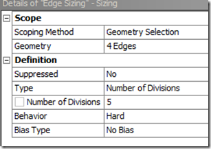
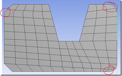
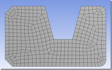
Eric Miller wrote a nice article back in February explaining the basics of using the mapped face meshing control available within ANSYS Workbench. Now…it would take a special kind of man to tell one of the directors of the company he works for that well…he just didn’t do a good enough job explaining it. Lucky for you all, I’m just that kind of man. “I have a different brain; I have a different heart; I got tiger blood, man.” – Charlie Sheen
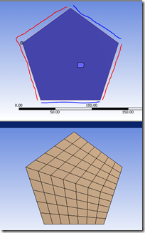
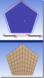
First of all, let’s start by discussing some behind-the-scenes operations being done. When you specify a side-vertex, the mesher internally concatenates the adjacent lines together to map the divisions of one block to another. So just by changing the side-vertex, you can ‘spin’ the mesh orientation around a given block. The images below show the difference as you pick different ‘side’ nodes. I had the local 3rd grade class draw lines over the map mesh source/target, divisions get mapped between same color lines.
So if we look at this a different way, the mapped face meshing is creating some virtual edges while still preserving the vertices for future use (e.g. applying displacements/forces). However, let’s say we really wanted to control some of the mapped divisions. We can do this using actual virtual topology to merge AND split edges (new feature in R13).
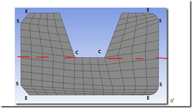
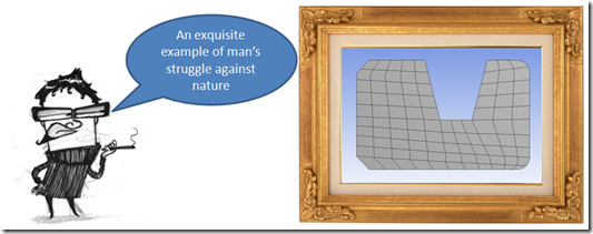
Here’s a picture of Eric’s example. It looks good enough, but for my discerning tastes I would prefer to have all of the divisions above the red dashed line match up, rather than having the divisions meander across the surface (technically speaking).
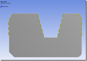
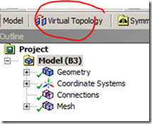
To get this, we just need to use some virtual topology tricks to split and combine the vertical edges. This can be done by inserting a virtual topology branch, available on the context toolbar when the ‘Model’ branch is highlighted. You then have the option of creating virtual cells or splitting edges.
 |
|
| To insert VT, Select the ‘Model’ level | When you have an edge selected, VT tools become available. ‘Split’ functionality available at R13 |
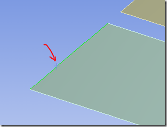
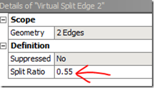
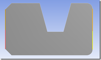
To combine two lines into one, simply select both of them and then click ‘Virtual’ Cell’. If you want to split an existing edge, highlight it and select one of the split options. If you select the ‘Split Edge at +’ it will split the line where you clicked on it:
 |
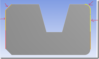 |
| Step 1: Split edges. Move ratio until it’s ~horizontal with bottom of notch | Step 2: Create virtual edge from split and neighboring edge (indicated by red arrows) |
Long story short….
- Use new virtual topology to fine-tune the geometry to meet your mapped meshing needs
- Anytime you’re dealing with curved edges, it may be worth your while to use a free mesh

