During this weeks webinar on Using APDL Snippets in ANSYS Mechanical a question came up about coordinate systems. I actually don’t remember the original question, but in answering it the question came into my mind: how do you get access to the ID of coordinate systems that you create in ANSYS Mechanical?
For a lot of items you can add to the ANSYS Mechanical model tree, you can attach a Command Object (snippet) and ANSYS Mechanical passes a parameter with the ID of the thing you want access to (material, contact pair, spring, joint, etc…). But there is no way to add a Command Object to a coordinate system.
So I dug into it and found something I didn’t know. The problem with discovering something like this and sharing it is that you either just uncovered something that can help a lot of users or you are going to embarrass yourself over something that everyone already knows. The idea of a blog is to be casual and informal, so let’s see which I did.
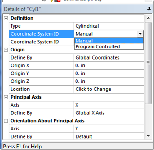
If you click on a user created coordinate system in ANSYS Mechanical The Detail View list two things in the first grouping “Definition”. They are Type and Coordinate System ID. The default for the ID is “Program Controlled” I’ve never clicked on it to see what the other options are. It turns out you can change it to “Manual”
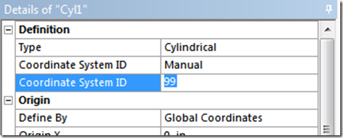
Once you do that it gives you a second “Coordinate System ID” line and you can put in whatever number you want there.
Problem solved. Just give your coordinate system whatever number you want and use that number in your macro. Couldn’t be easier.
Hopefully, this was helpful. If so, rate this posting at a 5.
If you already knew this little factoid, rate it as a 1.
– Eric


