I’m sure the question comes up for a lot of us from time to time, whether from one of our own offspring, another relative, or an acquaintance. “Just what is it that you do, anyway?” Typical answers might be something short and sweet, such as, “I’m an engineer.” A more detailed response might be, “I use a technique called finite element simulation which is a computer tool we use to simulate the behavior of parts or systems in their real world environment.”
You’ll probably find that people’s eyes glaze over and they start looking for someone else to talk to by the time you get to the end of that second quote above. In fact, I find that my extended family is much more interested in my brother-in-law’s surgery stories from the operating room than they are in my own triumphs and challenges in the engineering simulation world. Maybe you’ve had that same sort of reaction. You have probably noticed that there are a whole lot more medical dramas on TV at any one time than there are engineering dramas. They’ve got many characters from Marcus Welby on up to Dr. Ross on ER, Jack on Lost, to Dr. Grey on Grey’s Anatomy, with more than I can count in between.
We’ve got, well, Scotty. And even then I think Dr. McCoy got more air time.
So when my kids ask me what I do at work, I recall a scene from that late 1980’s to early 1990’s TV show The Wonder Years. In the episode “My Father’s Office,” Kevin asks his dad what he does for a living. His father responds in an angry tone, “You know what I do! I work at NORCOM.” As if that were a sufficient explanation. I suppose it was his way of saying, “It’s complicated. It can be high pressure. You might find it boring. It puts food on the table and a roof over our heads, though.”
Rather than reply that way, I’ve tried to come up with what is hopefully a better response. In fact, this concept constitutes the first portion of our Engineering with FEA training class, written by Keith DiRienz of FEA Technologies with contributions by yours truly.
I can’t guarantee that your audience’s eyes won’t glaze over by the end, nor that you’ll become the hit of the party, but this is free and you get what you pay for. This explanation can obviously be adjusted based on the audience, but it goes something like this:
Simple explanation:
–We have equations to solve for stresses and deflections in simply-shaped parts such as cantilevered beams.
–No such equations exist for complex shaped objects subject to arbitrary loads.
–So, using finite elements, we break up a complex part into solvable chunks, leading to a finite set of equations with finite unknowns.
-We solve the equations for the chunks, and that ends up giving us the results for the whole part.
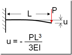
If we want more details, we can use this: As an example, here is a simple beam, fixed at one end with a tip load P at the other end. We have an equation to calculate the tip deflection u for simple cases:
In the above equation E is the Young’s Modulus, a property of the material being used and I is the moment of inertia, a property of the shape of the beam cross section.
For more complex shapes and loading conditions, we don’t have simple equations like that, but we can use the concept by dividing up our complex shape into a bunch of simpler shapes. Those shapes are called elements.
A useful equation for us is the linear spring equation, F=Kx, where F is the force exerted on the spring, K is the stiffness of the spring, and x is the deflection of one end of the spring relative to the other. If we extend that concept into 3D, we can have a spring representation in 3D space, meaning the X, Y, and Z directions. In fact, the tip deflection equation shown above for the beam fixed at one end can be considered a special case of our linear spring equation, solved for deflection with a known applied force.
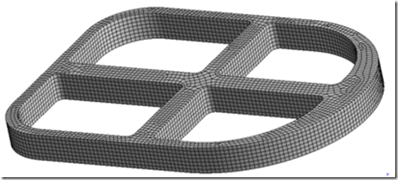
By assembling our complex structure out of these 3D springs, or elements, we can model the full set of geometry for complex shapes. The process of making the elements is called meshing, because a picture or plot of the elements looks like a mesh.
Using linear algebra and some calculus (stay in school kids!) we can setup a big series of equations that takes into account all the little springs in the structure as well as any fixed (unable to move) locations and any loads on the structure. The equations are too big to solve by hand by normal people so computers are used to do this.
When the computer is done solving we end up with deflection results in each direction for the corner points (called nodes) in each element. Some elements have extra nodes too.
From those deflection results, the computer can calculate other quantities of interest, such as stresses and strains. Further, other types of analyses can be solved in similar fashion, such as temperature calculations and fluid flow.
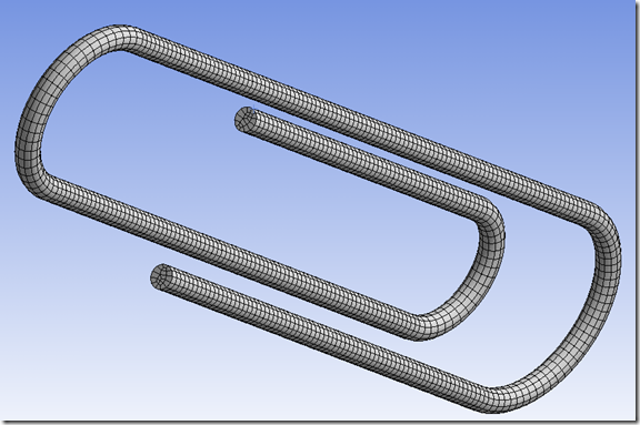
Here is an example using a familiar object that practically everyone can relate to. This plot shows the mesh:
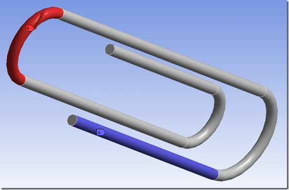
This is fixed in the blue region at the bottom and has an upward force on the left end. The idea here is that someone is holding it tightly on the blue surface and is pulling up on the red surface.
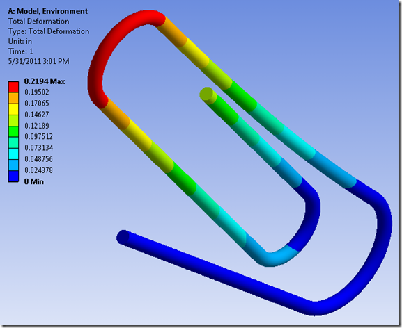
After solving the simulation, we get deflection results like this:
The picture above shows that the left end of the paper clip has deflected upward, which is what we would expect based on common experience with bending paper clips. Using our finite element method, we can predict the permanent deflection resulting from bending the paper clip beyond it’s ‘yield’ point, resulting in what we call plastic deformation.
Clearly there is a lot more to it than these few sentences describe, but hopefully this is enough to get the point across.
In sum, not as exciting as my brother in law’s medical stories involving nail guns or other gruesome injuries, but hopefully this makes the world of engineering simulation a little more accessible to our friends and family.
In the Wonder Years episode, Kevin ends up going to work with his father to see for himself what he does. I won’t spoil the episode, but hopefully you’ll get the chance to show your family and friends what it is that you do from time to time.

