Twice in the last week we’ve taken tech support calls in which the users questioned why their stress or strain results were being reported differently in Workbench Mechanical vs. the results from the same results file in /POST1 with ANSYS Mechanical APDL. After answering those questions it was pretty obvious that a Focus blog entry was in order. All we needed was a good, relevant example to demonstrate the issues and the explanation.
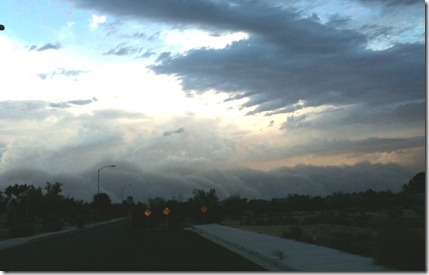
First glimpse of approaching dust storm. All photos by the author.
In case you missed it, the big story here in the Phoenix area this week was our monster haboob, or dust storm. If you’re not familiar with the term haboob, Wikipedia explains it here: http://en.wikipedia.org/wiki/Haboob. In order to have a humongous dust storm, you’ve got to have wind.

Stopped in a parking lot to take these pictures – the only camera I had was my phone.
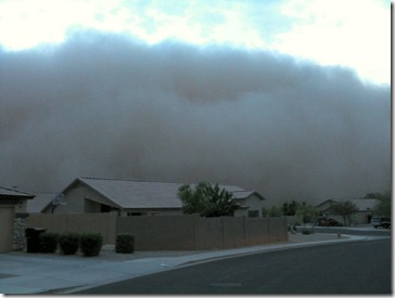
About 3 minutes after this picture was taken the dust storm arrived.
Wind tends to cause damage, but although our recent dust storm is estimated to have been 100 miles wide and up to 10,000 ft. high, we fortunately did not sustain much significant wind damage. Things that do tend to get mangled, however, are deployed patio umbrellas and portable expanding sunshades. These sunshades typically retract into a compact size and fit in a zip up carrying case. Many of us have collections of damaged sun shades that still work via creative application of duct tape, wire, etc. These inexpensive shades work great for keeping the sun off of us during birthday parties or other outdoor gatherings, but high winds tend to cause the metal members to bend and break, causing the shades to need some field engineering repair if not just a one way trip to the dumpster.
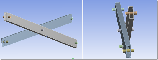
Here is a solid geometry representation of a typical portion of the frame of a representative shade. It consists of two rectangular hollow members, pinned to each other at the center, with pins at each end that in the full structure would be attached to additional components.
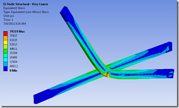
For simplicity, we fixed the pins on the right side to ground, while those on the left side have an upward bearing load applied to the upper pin and a downward bearing load applied to the lower pin. These loads tend to cause the members to bend at the central pin. The bearing loads in our example represent the effect of a strong gust of wind hitting the fabric canopy above the frame, with the load eventually reacting through the frame to stakes that attach the frame to the ground at the bottom. The main thing to note here is that the applied load is large enough to cause significant plastic deformation, not unlike what one might experience in the real world when one of these structures is subjected to a very strong wind.
Workbench Mechanical, Coarse Mesh, Peak von Mises Stress is 79,219 psi
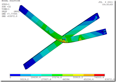
Same Results File in Mechanical APDL /POST1, Peak von Mises Stress is 83,873 psi
The issue here is that for our initial run with a very coarse mesh, when we view the von Mises stress results in the Mechanical editor and then compare them with the von Mises stress results obtained from the same results file in /POST1 in Mechanical APDL, we notice there is a difference (79.2 ksi vs. 83.9 ksi). Why is that? It has to do with how stresses are calculated. First let’s consider Mechanical APDL and /POST1. The original graphics display system is known as Full graphics. Fifteen or twenty years ago ANSYS, Inc. developed a newer graphics display system for MAPDL known as Powergraphics. There are several differences between these two display systems which affect results quantities.
ANSYS Mechanical APDL uses PowerGraphics by default, which among other things
A similar effect is seen with the von Mises plastic strain results:
Regarding the mesh densities used, the coarse mesh had an element size of at least 0.05 in. on the member hole at the high stress/strain location, while the fine mesh had an element size of 0.025 on the same hole. Another way to look at the mesh refinement is that the coarse model had 20 elements on the hole of interest while the fine mesh had 104 elements on the same hole. Clearly the coarse mesh in this example was way too coarse for engineering purposes, but this was selected for this article to ensure the effect of different results calculation methods was significant and observable.
So, the bottom line here is that if you see unacceptable differences in stress or strain results using different results calculation methods, it likely means that your mesh, at least in the area of interest, is too coarse. Try adding mesh refinement and check the results again. In Mechanical, you can try adding a Convergence item to a scoped result plot to at least partially automate this process. Just be careful that you don’t include any singularities in your desired convergence region.
If you were expecting a reference to the Kansas song, “Dust in the Wind,” well, I guess this is it. Fortunately we don’t seem to have many lingering affects of the big dust storm. The parking lot here at PADT has a thin layer of dirt that’s gradually disappearing. Once we get a good rain it will all get washed away.
Categories
Get Your Ansys Products & Support from the Engineers who Contribute to this Blog.
PADT’s Pulse Newsletter
Keep up to date on what is going on at PADT by subscribing to our newsletter.
By submitting this form, you are consenting to receive marketing emails from: . You can revoke your consent to receive emails at any time by using the SafeUnsubscribe® link, found at the bottom of every email. Emails are serviced by Constant Contact
Share this post:
Upcoming Events
Search in PADT site
Contact Us
Most of our customers receive their support over the phone or via email. Customers who are close by can also set up a face-to-face appointment with one of our engineers.
For most locations, simply contact us:

