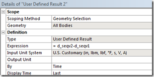
Wow, how time flies. I wrote an article ~5 weeks ago where I discussed User Defined Results in ANSYS Mechanical. One of the comments on that blog concerned being able to operate on results from multiple load steps, “e.g. stress in step 2 minus stress in step 1”. I responded that yes you could, and then like an idiot stated I would have another article written in “a week or so” detailing how to do this. My apologies Kjetil, I’m just now getting to this. Please don’t cancel your membership in the “Doug Oatis B-Movie + ANSYS Trick Fan Club” (I’d hate to be the only member left, plus your dues are non-refundable).
|

|
|
Do you know how exhausting it is to party like Motley Crue…by yourself?!?
|
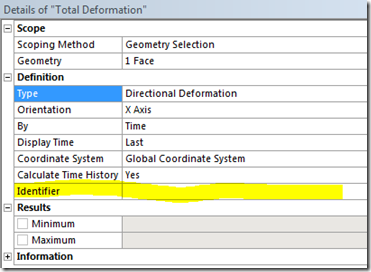
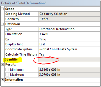
Anyways…back on topic. The ‘identifier’ is a line available in the Details Window for any result item.
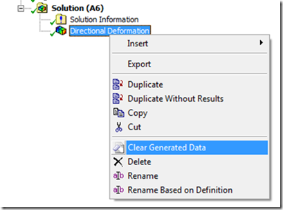
You can type in any kind of name in the cell to the right. Note that you need to enter the name in before you evaluate the result item, or else you will see that the right cell is gray (meaning you cannot edit it). If this happens, simply RMB on the result item in the tree and select ‘Clear Generated Data’. That will empty the ‘bucket’ of that result item and let you edit the details of it (it WILL NOT clear out your result file…unless you RMB on ‘Solution’).
 |
 |
|
Identifier cell after result has been evaluated
|
To fix, RMB and select ‘Clear Generated Data’
|
The benefit to using the identifier is that you can then create a user-defined result and type in an expression using these identifiers. Here’s the documentation section that discusses the available functions:
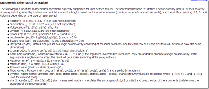 |
| Lots of words…but pretty intuitive function definitions |
The thing to note up there is the order you define the function depends on if you’re operating off of scalars or vectors (I’ll explain below). Let’s start out by first defining our UX and UY identifiers in our post-processing section:
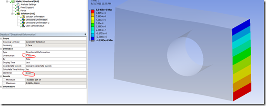 |
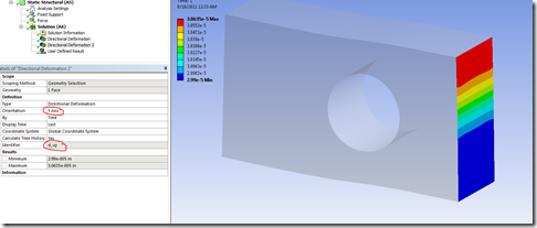 |
| X-Direction, Identifier = d_ux |
Y-Direction, Identifier = d_uy |
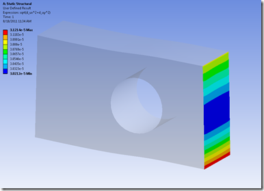
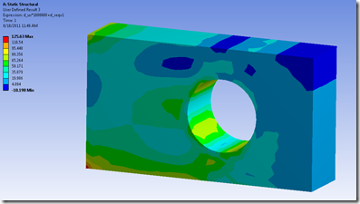
After I’ve defined both of these identifiers, I insert a User Defined Result. Next, I just type in the expression I want it to evaluate:
Going back to the issue of scalars vs arrays, let’s say I wanted to add some type of constant to one of my user defined results. In this case let’s assume I know that there’s an additional .5-in of rigid body motion that I want to plot. To do this, I need to understand that the identifier d_ux represents an array of information (node vs displacement). If I want to add a scalar (.5), I need to enter the expression d_ux+.5 (NOT .5+d_ux).
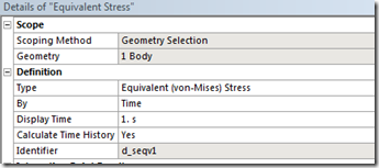
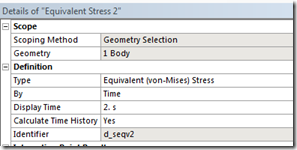
If I had multiple load-steps, I could scope a stress result to a specific time-point and then perform a similar operation. That would give me the stress increase due to the load change in between load-steps.
The thing to watch out here is to make sure that you stay consistent in what you’re operating on. Sure you can add stress and displacement together, but that’s not really going to get you anywhere.
 |
 |
| d_ux*10000+d_seqv…everyone knows that [in]+[psi]=[Oatis] |
For outstanding achievement in the field of flat-plate-with-hole-in-it analysis |
Also make sure that other details of identifiers you’re combining are consistent (e.g. coordinate system, integration option, etc).
For all those MAPDL users, think of this as exposing most of the *voper command within the Mechanical interface. The main difference is that you don’t have to worry about defining your array size, and it’s incredibly easy to get the data out (RMB > Export…rather than fighting your way through fortran or C formatters).
Enjoy!

