 |
| It may not have been that bad…and I might not look that cool |
I’ll first start by going over element birth and death. This functionality allows you to remove the stiffness of groups of elements from a load-step (clarification: it technically reduces the stiffness by the value defined with the ESTIF command, which defaults to 1E-6). I’ve typically seen it used to analyze some chip-level component where you have multiple assembly steps where the component is heated, stuff poured on it, cooled, heated back up to a different temperature, and so on. This functionality is accessed by using the ekill and ealive commands, which operate on the currently selected element set. I should also point out that you can use these commands on contact elements to simulate assembly processes by eliminating contact interfaces from being detected from step to step (PROTIP: not recommended for MPC-based contact).
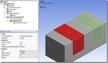
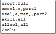
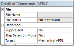
Next, how to enact in Workbench. The command snippets are fairly simple, the real leg work comes in selecting the elements you want to kill. This is typically done through named selections or selecting elements by material. The easiest way to use named selections is to scope the named selection to a body:
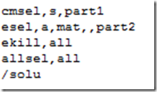
When a named selection is scoped to a body, the MAPDL input file contains a component consisting of elements. You can select these elements by using the command “cmsel,s,part1”. If the named selection is scoped to a keypoint, line, or area, the corresponding component will consist of nodes. You can ‘fight’ your way to the attached elements by doing a “esln” after you select the component (repeat as many times as you like in a *do loop). This can get confusing if you’re using surface bodies (meshed with shells) as the surface and body ‘look’ like the same thing…just realize that it’s all in the details (window).
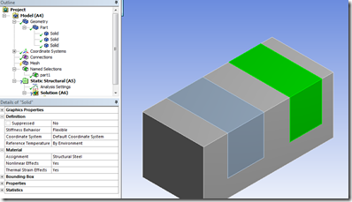
The other way (that I’m willing to discuss in this article) to select the elements is to ‘tag’ the material number in another command snippet.
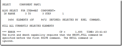
One thing that might happen is the auto-solver settings will have the inappropriate settings to properly support element birth death. If that happens, you’ll get the dreaded “an unknown error has occurred” in the message window. Looking into the ‘Solution Information’ window will then show:
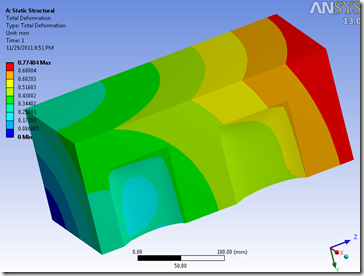
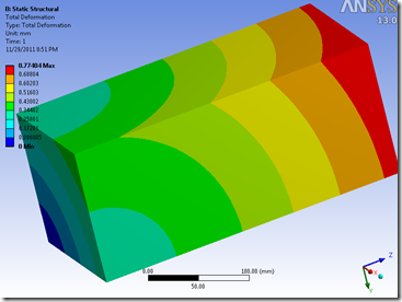
Here’s a comparison of the results with the command snippet active vs inactive:
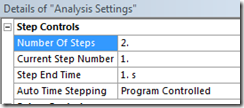
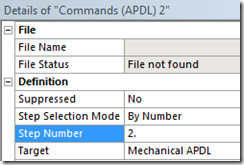
Now if you want to bring elements back into the model, you just need to insert a command snippet and scope it to the proper load step:
The second command snippet just needs to contain the command “ealive,all” in order to bring everything back. If you want to only bring back part of the model use the same selection logic as before. I’m not going to show any results, as everything is linear, it’s late, and my dog isn’t very happy about me writing this article. Hopefully you get the point.
In conclusion, some basic knowledge of MAPDL selection logic and load-step options within Mechanical, you can easily incorporate element birth and death into your model.

