Coordinate systems are one of those things that are fundamental to Finite Element Analysis, but that most of us do not think about a lot. They are there, but some users never fiddle with them. And some users are constantly futzing around with them. We thought it would be a good idea to do a quick review of how they work in ANSYS Mechanical. We will also go over the basics for Mechanical APDL (MADL) in case you need to work with snippets.
Why Coordinate Systems Matter
ANSYS cares a lot about coordinate systems because they allow the program to solve in a standard, global, Cartesian system while allowing loads, constraints, material directions, layer information, beam sections, joints, result values, and a whole slew of other important aspects of the model to be specified in unique coordinate systems. This avoids making the user do coordinate system transformations. At solve time, everything gets converted.
Since everyone reading this is an engineer, I’m going to assume that everyone already knows what a coordinate system is.
Coordinate Systems in DesignModeler and CAD Tools
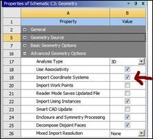
It is important to start at the beginning. Design Modeler and all CAD packages I’m aware of allow you to define some sort of coordinate system. Usually just Cartesian. In workbench you can import those coordinate systems into ANSYS Mechanical by clicking “Import Coordinate Systems” from the “Advanced Geometry Options” properties for the Geometry cell in you systems.
For DesignModeler, there is an extra step. Even if you turn on the import properties you need to dell DM which coordinate systems you want imported. But first, be aware that there is no “coordinate system” entity in DM. Instead it has planes, which is a coordinate system where you draw on the Z-normal plane.
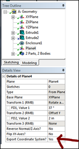
To make these available in ANSYS Mechanical, you need to scroll down to the bottom of the details for the planes you want converted over to coordinate systems, and set “Export Coordinate System” to Yes.
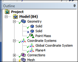
The following three images show setting it in DM, setting the property on the Project page, and how it shows up in Mechanical:
Creating Coordinate Systems in ANSYS Mechanical
In ANSYS Mechanical, coordinate systems reside in the Model Tree between Geometry and Connections. Once you define a coordinate system it becomes available for use with any other object that can use a coordinate system. This allows you to define it once, and then use it many times.
You always get a Global Cartesian coordinate system, called Global Coordinate System. It is Cartesian, has an ID of 0, and sits at 0,0,0. You can not change any of these values. Any imported coordinate systems will show up underneath the global.
To create a coordinate system you Right Mouse Button (RMB) on the Coordinate Systems branch and Insert->Coordinate System. Or, when you click on the branch you also get a Coordinate System toolbar:
Click on the three color triad icon and a new system will be inserted.
Let’s look at each of the options in the details view. But note before you go there, that the first set of group define a starting location and orientation, then you apply transformations in the last detail group in order to modify those locations.
- Definition Group: This group specifies the type and MAPDL number for the Coordinate System
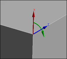
- Type: You can have the default Cartesian or Cylindrical here. The resulting coordinate system triads show up on your model like so. As you can see, Z is the rotational axis, Y is tangential an X is radial.
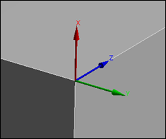
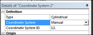
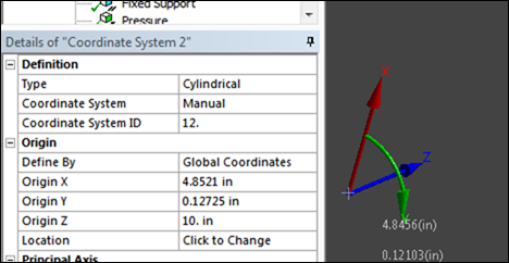
- Coordinate System: In my opinion this should say Coordinate System ID because this detail lets you decide if you want ANSYS Mechanical to assign the number that MAPDL will use, or if you will. Program Controlled is the default and is fine in most cases. If you need to wrote a snippet to work with a coordinate system then you should change it to “Manual” and Coordinate System ID will show up. Set it to any number over 11.
- Origin Group: This group defines where the center of the coordinate system is.
- Define By: You can specify a Geometry Selection or Global Coordinates.
- Geometry Selection: The cool thing about using Geometry Selection is that as you update your CAD model, the origin will shift with it. As with any geometry specification, you click on a surface, line, vertex or a collection of these. Mechanical will calculate the geometric center of the entity of entities that you picked and place the origin at that centroid. It will also shows the position in the global coordinate system below your geometry selection, but you can not change them.
- Global Coordinates: Here you simply put in an X, Y, and Z value in one of two ways. The easiest is to just type them in. Or, you click “Click to Change” for Location and pick the coordinate picker
 icon and move your mouse over your model. Mechanical calculates the point under the cursor (surface closest to camera) and displays it. When you click it will create a little blue cross on the geometry. Choose apply on Location an it will enter that point in as the origin. Kind of cool, if a bit inaccurate…
- Principal Axis Group: You need to tell Mechanical how to orient the coordinate system. By default it will align with the global. But you can use Axis and Define By to specify that any of the three axis are aligned with a global axis, or with a piece of geometry. Aligning with geometry is very useful because this is how you get coordinate systems aligned with your geometry. And when your geometry updates, that coordinate system aligns with the updated geometry. This is especially useful when specifying a coordinate system in a cylinder because you can pick the cylinder face for your Z axis and it will move with the cylinder.
Note that you can not specify align with Global –Z. If you want to do that you need to align with Z and use the transformation below to flip that.
One option for “Define By” is “Fixed Vector” This uses the current orientation but disassociates it from the geometry. - Orientation about Principal Axis Group: One point and a vector does not a coordinate system define. You have to specify an orientation around that principal axis. You do that just like the how you specify that principal axis. Define a global X, Y, or Z or a piece of geometry.
- Direction Vectors Group: These show the vectors for X, Y, and Z. You can’t change them (I wish you could) and they are not a parameter. But they are useful.
- Transformations Group: This area allows you to stack offsets, rotations, and mirrors.
You use the Coordinate System Toolbar to insert transformations into this group. They are executed in order from top to bottom and the resulting orientation and position are shown in Directional Vectors and Transformed Configuration.
There is a “Move Transform Up” and “Move Transform Down” icon as well in the toolbar to move the transformations around. There is also a delete to remove one.
Note: When you click on a transformation in the list, the coordinate system on your model is shown AT THAT STEP, not at the final position. This always confuses me. So make your change, then click on the last step to see it.
Using Coordinate Systems
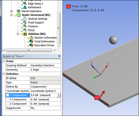
This is the easiest part. You simply choose one of your defined coordinate systems from a dropdown list when you create an object that is dependent on a coordinate system. Usually this is when you can define a value based Components rather than on geometry:
Do note that you can also use coordinate systems to transform directional result values. Simply pick the Coordinate system from the dropdown list. This is especially important when looking at hoop or radial stresses in a cylindrical part.
Coordinate Systems in ANSYS Mechanical APDL
Coordinate systems are huge in MAPDL. Nodes have them, elements have them, sections have them. Plus you can make a coordinate system active and every command you execute is done in that active coordinate system, and converted for you to the global. Very powerful.
If you do a search in help on “Coordinate System” you get hundreds of hits in the MAPDL manual. Way too much to go over here. We do recommend that you start with:
Mechanical APDL // Modeling and Meshing Guide // 3. Coordinate Systems // 3.1. Global and Local Coordinate Systems
It explains the types, the math, and the commands needed. Read that, then move on to 3.3, 3.4, and 3.5 which talk about nodal, element and result coordinate systems.
Some key things every user should know are:
- All coordinate systems are defined by a number. 0-10 are reserved by MAPDL for its use. Users can do 11 or higher.
- MAPDL has 6 default coordinate systems:

0 = Cartesian
1 is cylindrical down the Z axis
2 is Spherical
4 is Cartesian, same as 0
5 is Cylindrical down the Y axis.
6 is Cylindrical down the X axis (not shown)
I have no idea what happened to 3 or why 4 is the same as 0. - When you change the active coordinate system with CSYS, all commands that involve coordinates get transformed into that coordinate system. So:
local,11,1,2.5,0,0,0,90,90
n,1,10,10,10
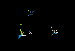
Actually makes a node at 12.5,9.8481,1.7365 in the global coordinate system. - You can show local coordinate system with /psymb,csys,1
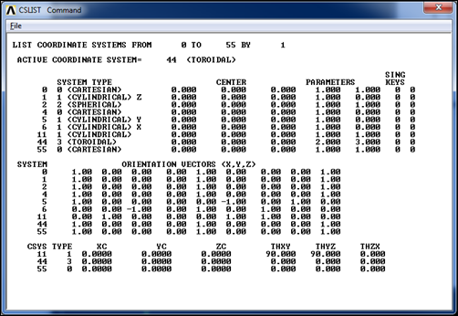
- You can list your coordinate system definitions with CSLIST:
- Only Cartesian and cylindrical are supported in ANSYS Mechanical, so if you need to use spherical or Toroidal you need to use snippets
Thoughts
Make sure you understand how Mechanical is using coordinate systems by bringing your models up in MAPDL. Look at your nodes and see if they are rotated and how. Check the coordinate systems with a CSLIST. Make sure you feel comfortable, don’t take it for granted.

