The ANSYS Mechanical APDL solver has a lot of contact options. KEYOPT(12) this and KEYOPT(4) that. I’m sure we all read Chapter 3.9 of the Contact Technology Guide to understand and remind ourselves on all these options. I know here at PADT we always do so on the third Tuesday of every month… OK, maybe not.
But as fate would have it I was looking something up in there the other month and came across one of the newer options: Surface Projection Based Contact. It is on of those little options that can make a big difference, so I thought I would put it on the list of potential Focus articles, and it just bubbled to the top.
Contact and Contact Detection
The way contact works in an FEA program is that you define a contact and a target. The program goes in and calculates if a point on the contact surface is near, touching, or inside the surface or point that is the target. If they are touching or inside forces are calculated acting on the contact points in the normal and tangential (friction) directions. You use a slew of options to determine what that algorithm looks like. But hey all need to know what the gap or penetration is between the contact and target surfaces.
What is important for this article is how the program chooses those contact points to look at and, if needed, calculate forces on.
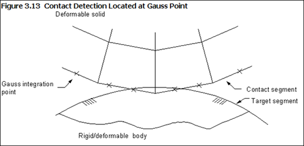
The default (KEYOPT(4) =0) is to use the gauss points on the elements. Here is a great illustration from the online help:
Gauss points are good because there are more per element than nodes and calculations are done at the gauss points anyhow. The down side is that if you have a lot of curvature or even a corner, the true surface of your contacting part can penetrate into the target.
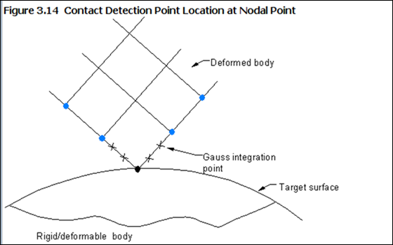
For those times when you do need to control things at the nodes, you can use KEYOPT(4) = 1 or 2.
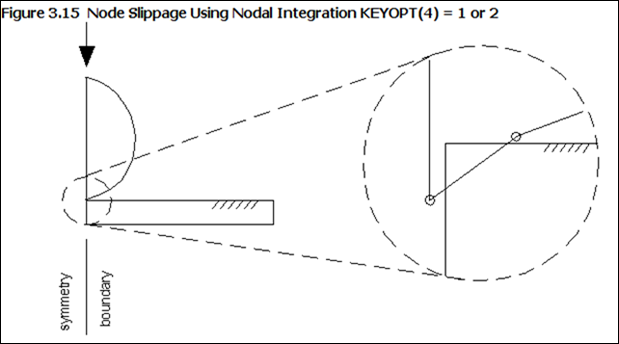
The down side is that the program now has to do a lot more calculations to make things happen at the nodes, and it has to calculate normals for the contact or target surface. Plus there are fewer points. But the worst thing that can happen is node drop off if your mesh is not refined enough:
KEYOPT(4) = 3
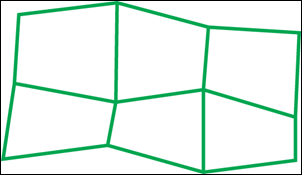
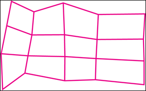
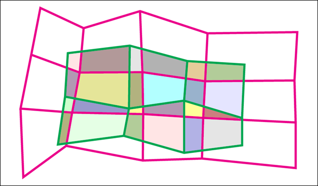
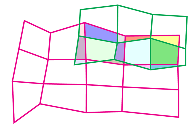
Sometimes using points for contact results can cause problems. The node penetration or drop off being good example. it can also be an issue if there is a lot of “overhang” on an element. So the developers at ANSYS have added a third option, the Surface Projection Based Contact Method, or KEYOPT(4) = 3. What the method does is look at the element faces on each side of the pair, contact and target, and calculate the union of each. If we look at the following example you can see it. The green mesh are the contact surface elements, the cyan mesh is the target. If we put them on top of each other, each unique area becomes a surface projected contact area, shown in the third image.
So instead of calculating penetration/gap at each integration point or node, it calculates an average value for each overlapping area. This can really make a big difference when you have the contact hanging off of the target, as shown in this illustration:
Advantages
So the three big advantages of this approach are:
- In most cases it provides a more accurate calculation of contact traction and stresses for the underlying elements.
- It is less sensitive to which side you designate as the target and which ones you designate as the contact surface. This is because you end up with the same projected areas.
- Moment equilibrium is satisfied if there is an offset between the target and contact surface and friction is turned on.
- Contact forces do not “jump” when a contact node slides off of the edge of a target surface.
Disadvantages
No surprise, it is not perfect or it would be the new default. The disadvantages are:
- The method is computationally more expensive because you usually have more contact areas then you would have contact points with the other method, especially if the target mesh is refined giving you more areas.
- The penetration or gab is an average value so when a model has corner or edge contact, the nodes on the edge or corner will penetrate into the target surface. This is similar to what you see with the gauss point detection method. More refinement usually solves this.
- Free thermal surfaces don’t work with it. (What is a free thermal surface, I forgot as well. It is a feature in thermal contact, Chapter 7.1 of the Contact Technology Guide. It is now on the Focus to-do articles list)
- You can not use a primitive for a rigid target. This makes sense if you think about it. If you use a primitive there are no element faces to find the overlap on.
- 3D contact and target elements can not have partially dropped midside nodes. They either all have to be there or none.
ANSYS Mechanical
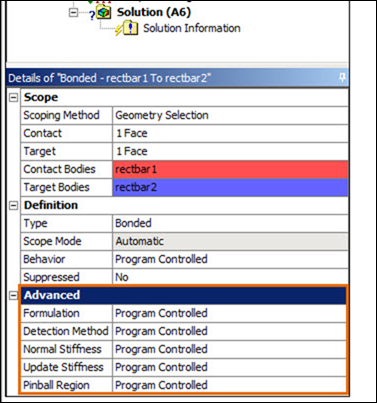
Although we have been talking about how things work in the solver, and the KEYOPTs used in Mechanical APDL, you can still access this through ANSYS Mechanical. Any contact par will have an Advanced portion of its details view. In there you can access most of the KEYOPTs, including the Detection method, which is KEYOPT(4).
And here is the drop down for Detection Method. The last one, Nodal-Projection Normal from Contact is actually Surface Based Contact Projection:
Recommendations
The best way to get a feel for this is to find a couple of models you have already run with one of the other contact methods and run them with this option turned on and take a look at run time per iteration, number of iterations for convergence and the resulting stresses in the contact area. If you have flat, fairly refined contact/target meshes with no overhanging, you should just see things take longer. But if you do have a curvy surface, a corner, or a coarse mesh you should see better performance and accuracy.

