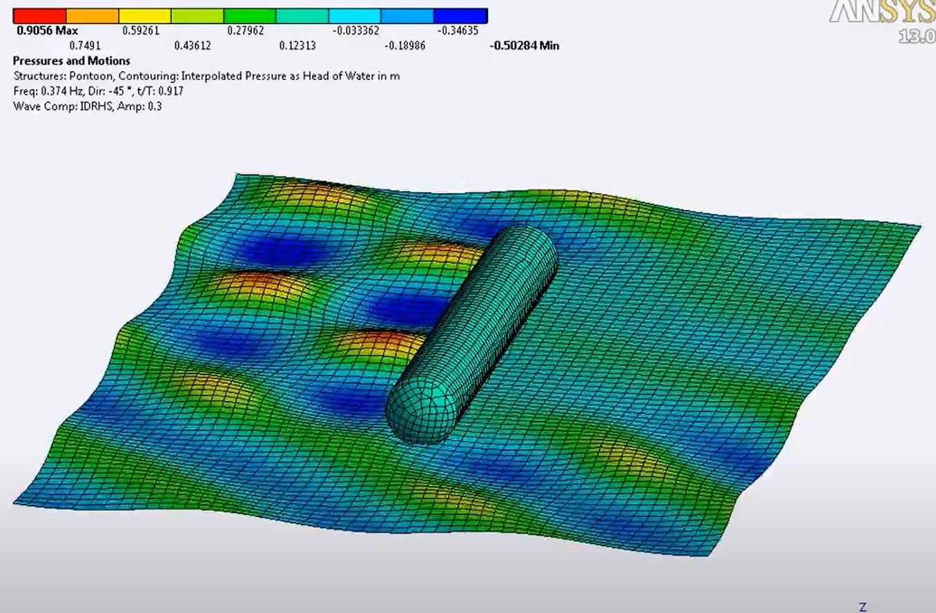
Maybe you’ve seen AQWA show up in the list of ANSYS products to be installed on your computer, or maybe you’ve seen it as a topic in the ANSYS Help System and you otherwise wondered about it. Is it related to Aqua Man or perhaps Aqua Lung? Not at all. If you are not familiar with it, AQWA is a tool for simulating wave and current as well as wind loads on marine vessels and structures.
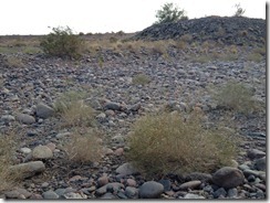
Truthfully, although we are located in the Sonoran Desert, we have some great lakes within a short drive of Phoenix, let alone Tempe Town Lake just a few miles from PADT, and lakes Powell and Mead up on our northern and western borders with Utah and Nevada offer miles and miles of incredible scenery. However, most of our rivers are dammed for water storage and irrigation so it’s not uncommon to see river beds with no water in them for most of the year. A standard joke is that Arizona is the place where rivers and bodies of water are not associated with each other.
The bottom of the Salt River, aka Rio Salado, which flows through Phoenix (Sometimes)
The Nav System Knows it as a River
Yes, it does rain in Phoenix. Just not often. This storm caused over an inch of rain in some places:
This is more of a typical day. No rain in sight:
You may be wondering why we have an interest in AQWA here in the Sonoran Desert. The short answer is that we support an organization working on alternative energy sources, including offshore wave power. As a result, we’ve had to become familiar with the ANSYS AQWA suite of tools.
Incident Waves on a Moving Ship:

At version 14.0, the main part of AQWA, hydrodynamic diffraction, is integrated with ANSYS Workbench. In a hydrodynamic diffraction analysis, we are calculating the response on our structure due to incoming and receding waves. The effects on the water due to its interaction with the structure are also included. It’s also possible to perform a hydrodynamic time response analysis within the Workbench framework. Interaction with permanent structures such as piers and breakwaters can be included as well.
The use of Workbench means we can use ANSYS DesignModeler to construct and edit our geometry, including a slice at the waterline and formation of a multi-body part, both of which are needed for AQWA. It is somewhat integrated with Workbench Mechanical, in that it’s possible to map pressure and inertia loads from AQWA into Mechanical for a detailed structural analysis, but it’s somewhat of a manual process currently. For those familiar with the ANSYS APDL command language, it’s fairly straightforward.
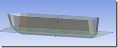
Geometry Split at the Water Line in DesignModeler:
AQWA can also be run in stand-alone mode, which opens up additional capabilities while still taking advantage of DesignModeler surface geometry or another source. The various modules have creative names such as AQWA-Line, AQWA-Librium, AQWA-Fer, AQWA-Drift, and AQWA-Naut. Besides hydrodynamic diffraction, one can look at the effects of mooring lines, cables and tethers and varying wave and wind loads on structures. Special elements are included which facilitate the simulation of ‘stingers’ or articulated trusses which are used to connect underwater piping to floating vessels. Fenders can also be modeled to allow for interaction between floating and floating or floating and permanent structures that may come into or out of contact.
Geometry of the structures modeled consists of surface models which are meshed with shell elements. Meshes must be relatively coarse compared to what most of us who normally perform structural analyses are used to. Small geometric details usually need to be omitted to keep the mesh sizes down, but that’s not really a problem as we are trying to accurately predict interaction between the fluid and the structures, not stress concentrations or other localized results within AQWA.
In addition to plots and animations of interacting waves and pressure distributions, many other results quantities are available including cable forces, RAO’s (response amplitude operators), drift coefficients, shear force and bending moments, and other quantities used in the industry. These quantities are useful to those developing sea-going vessels as well as for those in the oil and gas industry involved in developing Floating Production, Storage, and Offloading (FPSO) structures and Tension Leg Platforms (TLP’s), etc.
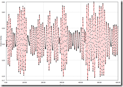
Forces on Two Mooring Lines vs. Time:
Floating Structure Lateral Position vs. Time:
If any of this looks like a tool that would be useful for the types of projects you work on, by all means contact your local ANSYS provider for more information. You’ll want to plan on taking the AQWA training class, which we have found very useful.
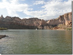
One of the lakes along the Salt River. Indeed there is water in the desert, if no ocean:

