

In part I if this series, we saw how to use Newton-Raphson residual plots as an aid to vanquishing convergence difficulties in ANSYS Workbench Mechanical. In part II, we will see how to quickly launch the ANSYS Mechanical APDL user interface to plot elements that have undergone too much distortion, thereby resulting in a convergence failure. Several problems can cause convergence failures, but one that can be particularly frustrating is elements that have undergone too much distortion.
Currently there isn’t a way to isolate and view elements that have triggered a convergence failure due to too much distortion within the Workbench Mechanical user interface. Fortunately we have access to the older ANSYS Mechanical APDL interface, which does allow us to select and visualize elements that have undergone too much distortion. This can be useful in that it tells us exactly where in the model the elements are failing. Hopefully we can use this information to take corrective action in Mechanical such as making local mesh modifications, adding more details to geometry, etc.
So, how do we do this? Rather than try to give a lesson on how to use the Mechanical APDL interface, we’re just going to give the commands needed to be clicked with the mouse or typed in. We’re following the K.I.S.S. principal, meaning Keep It Simple, Silly.
The procedure to follow includes these steps:
1. Identify the directory in which our results file resides.
2. Launch ANSYS Mechanical APDL.
3. Point to the results file identified in step 1.
4. Modify the nodal coordinates so they are in the deflected state at the point of convergence failure.
5. Plot those error-causing elements.
We will now go into more detail using a model that has convergence trouble. This model solved successfully for the first 4 substeps, but on the 5th substep the solution failed to converge. We get this error in the solver output (Solution Information):
*** ERROR *** CP = 2872.649 TIME= 16:29:51
One or more elements have become highly distorted. Excessive
distortion of elements is usually a symptom indicating the need for
corrective action elsewhere. Try incrementing the load more slowly
(increase the number of substeps or decrease the time step size). You
may need to improve your mesh to obtain elements with better aspect
ratios. Also consider the behavior of materials, contact pairs,
and/or constraint equations. If this message appears in the first
iteration of first substep, be sure to perform element shape checking.
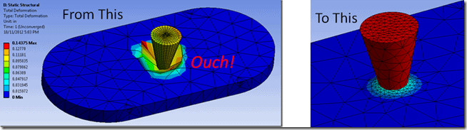
Looking at the model, we see we have an indenter that is being pressed into a block of material. The indenter is steel and the block is aluminum. Both have nonlinear material properties defined.

Total deformation for the last converged substep looks like this:

The unconverged results show that we have some elements that have large nodal deflections:

So, our error message tells us that one or more elements have become highly distorted. Which elements are they? The following procedure will show us how to view those for sure, using Mechanical APDL.
Here are each of the 6 steps mentioned above, in detail:
1. Identify the directory in which our results file resides:
We do this from the Workbench window, by clicking on View > Files. Scroll down in the resulting list of files until you find file.rst, the ANSYS Result file. The location will be listed in the resulting information, but the text is not selectable. To make it easier, right click on the file.rst row and select Open Containing Folder.

From the top of the resulting Windows Explorer window, select the folder path and right click > copy.

2. Launch ANSYS Mechanical APDL:
Click Start > All Programs > ANSYS 14.0 > ANSYS Mechanical APDL Product Launcher. In the resulting window, paste in the directory path in the Working Directory box:

Click the Run button at the bottom of the window. The Mechanical APDL user interface will start.
3. Point to the results file identified in step 1:
Click on General Postproc on the left, then Data & File Opts. In the resulting Data and File Options window, click on the […] button below Read single result file:

You should see the result file, file.rst, available in the resulting window. Click on that file, then click Open. Click OK in the Data and File Options window.
We need to read in one set of results to load the model into the Mechanical APDL database. Click General Postproc > Read Results > Last Set.
4. Modify the nodal coordinates so they are in the deflected state at the point of convergence failure:
Let’s plot the elements so we can see the model (this will show the elements with nodes in the original, undeflected positions). We’ll just have you type in the command to make the element plot: in the input line near the top of the window, type eplot, then return.

The plot will show in the default “front” view, looking down the global Z axis. Note that if weak springs are on in Workbench Mechanical, you will see these as line elements pointing away from the model in a few places.

The nodal modification is performed in the preprocessor. Click on the Preprocessor command on the left side of the window. Type in this command in the input line to modify the nodal positions to those of the unconverged (last set) of results:
upgeom,,,,file,rst
Plot the elements again. You should now see the deflected nodal positions.

Using the view controls over on the right side, we can rotate and zoom in. A short cut is to use the right mouse button to box zoom and Ctrl + Right Mouse Button to rotate the model. Now we can better see where the deformations are occurring. We still have all elements selected and plotted, so the next step will be to filter the plot to show the error-causing elements.

5. Plot those error-causing elements:
Shape checking of elements consists of two levels, warning and error. The solver will not continue if any elements exceed the error level. Shape checking is discussed in detail in section 13.1 of the Theory Reference in the ANSYS Help. We have the ability to plot both warning level elements and error level elements, using this procedure:
On the left side of the window, click on Meshing > Check Mesh > Individual Elm > Plot Warning/Error Messages.

With all boxed checked, this is the resulting plot in the front view. “Good” elements are displayed in blue, “warning” elements in yellow, and “error” or failed elements are shown in red.
When the elements are very highly distorted, their surfaces can’t always be displayed and it looks like there is a hole in the model. This won’t always happen depending on how highly distorted the elements are, viewing direction, etc..


If we uncheck the Good Elements (blue) box, then only the warning and error elements are displayed.


When you are done viewing the elements, click on the Quit button near the top, and exit without saving to get out of Mechanical APDL.
So what does all this tell us? For this model, the elements below the indenter body are experiencing too much deformation (red elements). Some elements in the indenter body are at the warning level but not the error level (yellow elements). The fix could be to apply the load more gradually (more substeps), refine the mesh at this location, or maybe a combination of both. In this case we also changed the Workbench Mechanical shape checking from Standard to Aggressive Mechanical.


