 The STL file is the linqua-franca of the prototyping world, the file format that all geometry creation tools write, and that all prototyping systems read. When you make a prototype it will be an exact copy of your STL file. If your file is not accurate, then your prototype will not be accurate. If there are errors in your file, you may not be able to get a prototype made. Therefore, a little bit of time understanding STL files and how to create a good one is a good investment that will pay off in the long run.
About STL Files
When additive manufacturing was just starting the manufacturers of machines faced a problem – they needed a way to get 3D solid models from a large number of CAD systems to their machines for processing. The common file format for geometry interchange, IGES, was not robust enough because of toleranceing issues. Writing a program to slice up each CAD format was also not practical. So they looked at the problem and realized they did not need exact mathematical models made up of NURB, Bezier, or analytical geometry. The algorithm that sliced up each layer just needed polygons on the surface. So the STL file just needed to have those polygons. And the STL file was born.
Lets talk about that slicing process. If you remember, almost all additive manufacturing processes work by creating stacked layers that are a cross section of the part you want. To build the part you must slice the geometry in software, calculating that cross section. Doing the intersection of a plane with a complex NURB surface is hard math, but the intersection with a triangle is very easy and results in a line segment. This makes creating the path for each layer much easier.
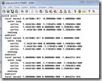
STL stands for STereoLithography, or Standard Tessellation Language, depending on which source you check. It was invented for 3D Systems by the Albert Consulting Group way back in 1987 to support the first Stereolithography machines. The format describes a collection of facets, or polygons. Each polygon is defined by a normal “outward” vector and the vertices that define it. Although the format supports more than three vertices per facet, in practice everyone uses three, defining a triangle. The file can be a text file (ASCII) or a binary file.
Users almost never have to worry about the file because the programs they use to create their geometry automatically generate STL files in the proper format. If you do need to write your own routine to output an STL file, it is fairly simple.
Faceting
 The way an STL file is made is the program that creates the STL file goes through the topology of the model and meshes it:
1: First it puts points on all of the shared edges of all the surfaces
2: Then it creates triangles on each surface
The algorithm used to create the facets varies from program to program, but most of them use the same routines they use to make facets for the 3D graphics you see on your monitor.
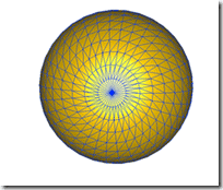
There are two things to note about faceting. The first is that each corner must be coincident with at least one other corner. No corners can touch the edge of another triangle. The second is that a triangle is flat and your surface can be curved. To make your curved surface look curved you need enough triangles to make it appear like a continuous surface.
Leaky Geometry
The most common problem these days with STL files is leaky geometry. When your CAD tool creates the STL file your solid may not be a true solid in that you have holes in your topology. This can be caused by gaps, ill-defined curves and surface, or corners (vertices) not lining up. If you cut out the triangles and glued them together then filled the resulting object with water, the water would leak out.
You CAD package can make leaky STL files if it has loosened up the tolerances on the geometry modeling to the point where edges on its surface do not really line up. They trick themselves into accepting this through some hand waving inside their database, and it really is not a problem till you want to do something with the surfaces. Something like make an STL file.
One way to fix this problem is to clean up the original geometry. Run diagnostics on it and see where there are holes. You should do this anyway because in the end, a messy solid will cause problems when you make your drawings, calculate tool paths, or try and do simulation.
If that is not an option, you can use repair software. If you use an RP service provider, they should be able to repair most STL files. But if you constantly need them to do so, you should really look at changing your modeling practices or investing in some repair tools.
If you are doing your own prototyping, you have two good options. The first is free: Meshlab. It is an open source tool for working with faceted geometry and has repair and diagnostic capabilities. It does a lot so the interface can be a bit confusing, but it is free. If you want to save time and probably money in the long run, we recommend that you purchase a copy of SolidView. It is purpose built for repairing STL files and can really cut down on your repair time.
Faceted Geometry
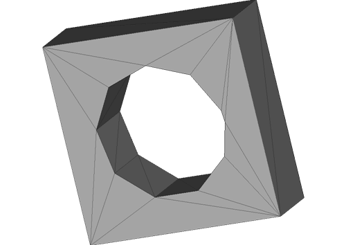
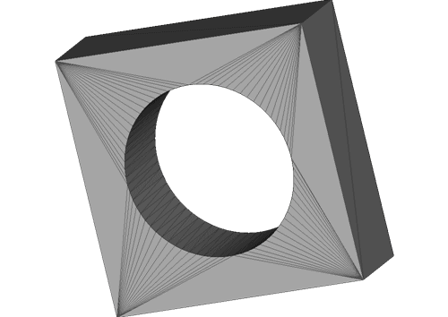
Even if your prototyping tool can read your geometry and make a valid part, it may come out looking all clunky because your geometry is to faceted. As discussed above, the STL file is made up of triangles. If you have too few triangles on a curved surface then it comes out looking all flat and ugly. Here is a simple example:


The key to controlling this is to set the options in your CAD package to create more facets.
This is such an important topic, we actually have a whole posting dedicated to it:
STL File Tolerance: A Short Explanation of Faceting and Chord Height
In the old days we tried to minimize the number of triangles in an STL file because that file had to be uploaded, often via a modem. But now we can email very large files, so you can make some pretty big STL files. Don’t go crazy, but don’t sacrifice surface quality either.
Degenerate Triangles and Inverted Faces
It is very rare for a CAD tool to create bad triangles, but it happens every once in a while. When trying to create a build from an STL file you might get a “Degenerate Triangle” or “Inverted Faces” error message. There is not much you can do with this other than try one of the repair tools mentioned above or try and fix your underlying geometry. If you get this type of error, there is something very wrong with your solid model.
Feature Sizes
Another problem that people often run across is that some of their small features do not show up on their prototype. This can be because their STL file is not refined enough and that can be solved by tightening up the tolerance on their STL file creation. If that does not work, the feature may just be too small for the technology. Take a look at what the true machine resolution is. Make sure that is is smaller than your smallest features.
Make an Investment in Productivity
Having a bad STL file can really slow down the rapid part of Rapid Prototyping. That is why PADT recommends that you take the time when you create your solid models to make good, robust, water tight solids that can be used down stream. If you have nasty geometry or a less than precise CAD tool (can anyone say CATIA) you may have to invest in a repair program like Meshlab or SolidView. Some up-front investment will pay in the long run, especially when you need that prototype first thing in the morning.


