[updated on 6/18/14 with images of an optimized bracket]
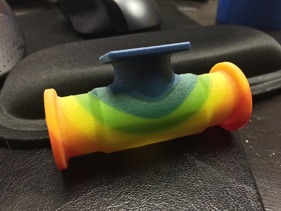
When we announced that Stratasys had released a color 3D Printer, I promised that I would figure out a way to get an ANSYS Mechanical or Mechanical APDL solution printed in 3D as soon as possible. Here it is:
Pretty cool. I posted this picture on our social media and it got more retweets-shares-comments-likes-social media at’a boys than anything we have ever posted. So there is definitely some interest in this. Now that the initial “WOW!” factor is gone, it is time to talk technical details and share how to get a plot made.
Stratasys Objet500 Connex3
There have been some machine around for some time that can print colors. Unfortunately they used a process that deposited a binding agent (fancy name for glue) into a bed of powder. The glue could be died different colors, allowing you to mix three base colors to get a color part. The problem with that technology is that the parts were faded and very fragile. On top of that the machines were messy and hard to run.
With the Objet500 Connex3 from Stratasys, we now have a machine that makes robust and usable prototypes, that can be printed in color. The device uses inkjet print heads to deposit a photopolymer (a resin that hardens when you shine ultraviolet light on it) one layer at a time. This machine has four print heads: one for support, one for a base material, and two for colored material. The base material can be black, white, or clear. Then you can mix two colors in to get a 46 color pallet on a given run. Download the brochure here for more details on the device, or shoot us an email.
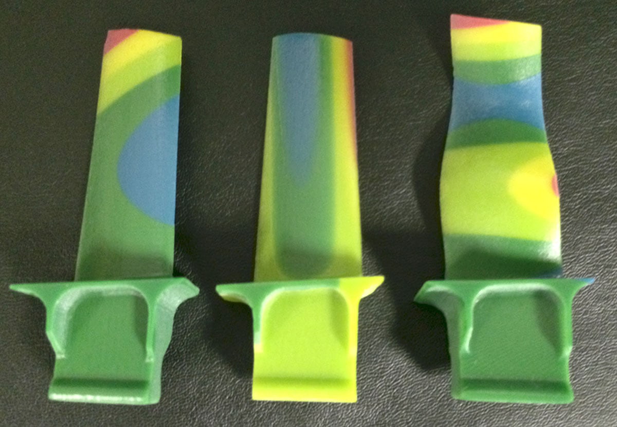
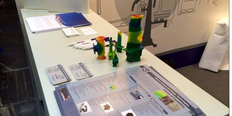
As an example of how to use this technology, we took the results from a modal analysis on a simple low-pressure turbine blade (from a jet engine) and plotted out the deflection results for the 1st, 3rd, and 7th mode. The 7th mode also includes the exaggerated deflected shape.
[Added 6/18/14]
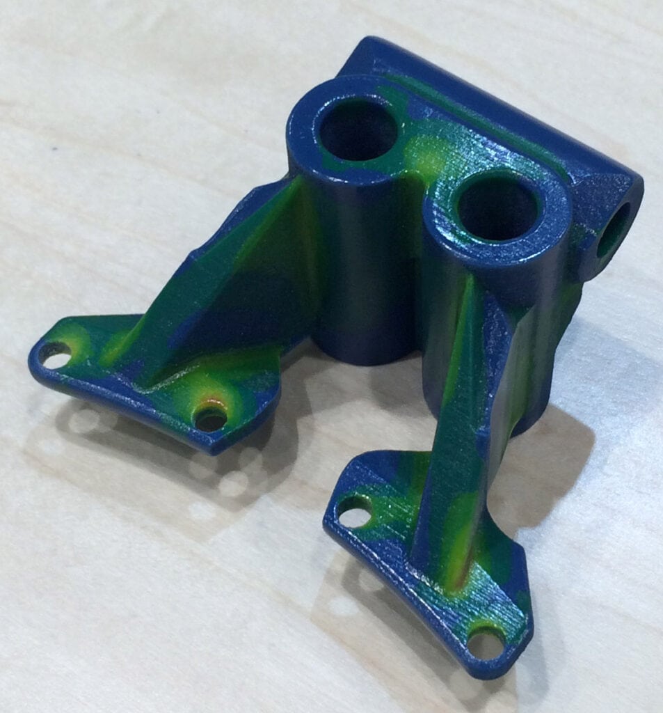
We recently combined ANSYS and Stratasys products for an optimization test case for a customer. We used Toplogoical optimization to remove chunks of material from an aerospace mounting bracket. Then we 3D plotted the results to share with the international team looking at using this process to design parts that are lighter because they are not constrained by traditional manufacturing requirements. Here is what the first pass on the part looked like:
Getting a Printable File
Almost every Additive Manufacturing machine, from 3D Printers to Manufacturing Systems, use an STL file as the way to define a part to be made. The file contains triangular facets (a mesh) on the surface. The problem is that this file does not have a standard for defining colors. The way that we get around this is you make an STL file for each color you want, sort of an STL assembly. Then when you load the files into the machine, you assign colors to each STL object. That is great if you are printing an assembly and each solid object in you Model is a different color, but gets a bit dicey for a results contour.
So, we need a way to get an STL file for each color contour in your plot. Right now non of the ANSYS products output an STL file. Needless to say we have been talking with development about this and we hope there will be a built in solution at the next release. In the interim, we have developed two methods.
Method 0: Have PADT Print your Part
Before we go over the two methods, we should mention that we offer almost every RP technology as a service to customers, including the new Objet500 Connex3. We have written a tool that converts ANSYS MAPDL models into STL’s that represent color bands. It comes in two parts, a macro that you run to get the data, and a program we have that turns the data into STL files.
So the easiest way to get a Color 3D Plot of your results is to:
- Download the macro ans2vtk.mac and run it. Instructions are in the header.
- Email 3dprint@padtinc.com and let us know that you want a Color 3D Print, and what units your part is and scale factor, if any, to apply to your part. They will let you know how to send the file.
- We will generate a quote.
- You give us a PO or a credit card
- We pre-process the part and show you the resulting contours, making sure it is what you want
- We print it, then ship it to you.
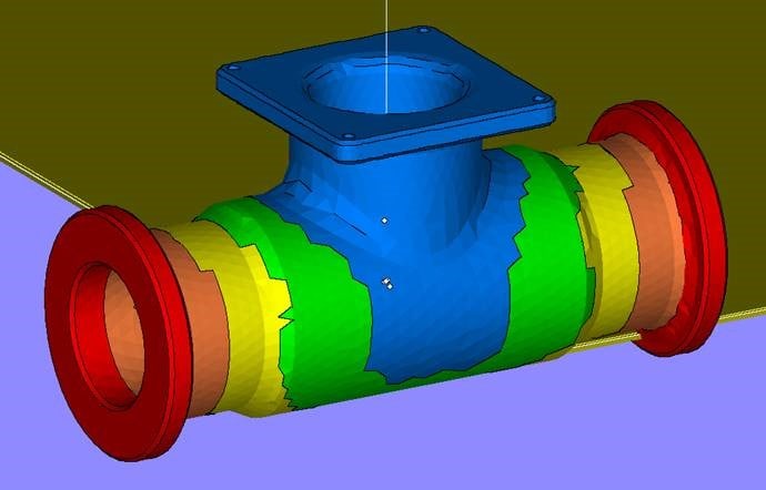
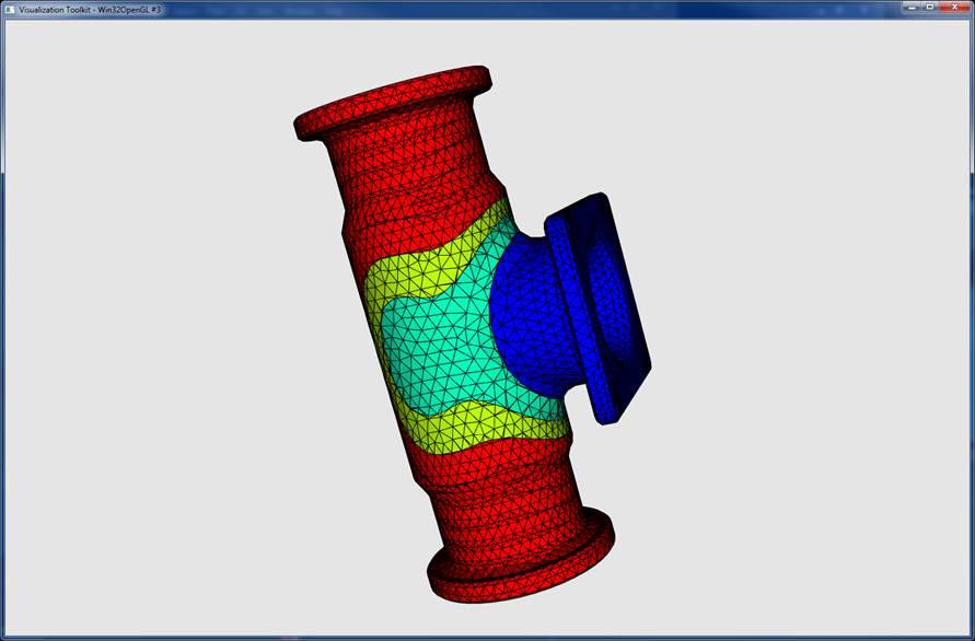
This is a screenshot of the model in our internal tool:
Method 0.5: Use the PADT Script
If you own a Connex3 and are not a service provider, we would be happy to share the internal script that we use with you. You would follow the same process as above, but would run the script yourself to make the STL files. You will need to install some opensource tools as well. Email me to discuss.
Method 1: RST to CFD-Post to Magics
This is how we did the first sample models, because it works out of the box and required no coding. To use it you need to have a licence of ANSYS CFD-Post and Magics from Materialise. CFD Post outputs a color facet file in the VRML2 format, and Magics can convert that into a bunch of STL file.
NOTE: For this to work you need Magics and your contours need to be pretty simple. A complex part won’t work because Magics won’t be able to figure out the STL volumes.
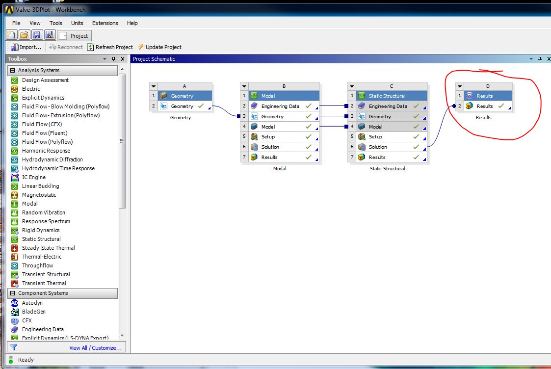
We start by attaching a CFD Post object to our model:
Open up CFD Post and make a plot you like. If you don’t know ANSYS CFD Post, here is an article we did a while back on how to use it to post ANSYS Mechanical and Mechanical APDL results.
Set the number of contours to a smaller number. You can have up to 46 colors, but that means you have to make 46 separate STL files by hand. I picked 7 contours, which gives me 6 colors:
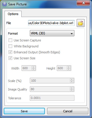
Now simply go to File > Save Picture and select VRML as your format. Note, it will bury the plot way down in your project directories, so I like to change the path to save it at the top level of the directory:
The next step is to read the file in to Magics.
In Magics, you can select facets by color and write each one out as a separate STL file.
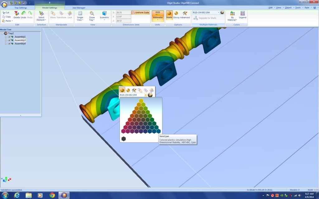
Once you have done that, go in to the Objet Studio Software that came with your printer and assign colors to each STL file. We just kind of eyeball the closest color to the original plot:
You can see here that we actually printed 3 at a time, just made copies and we only had to define colors on the original. Then Print.
Here is what it looks like in the printer when it finished. We ran some other parts next to the three valves:
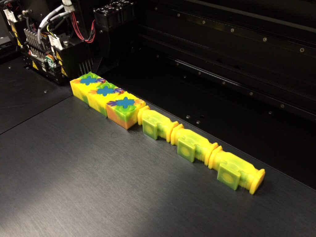
You’ll notice it looks all yellow. That is the support material. It is water soluble and we just wash it off when the part is done.
Method 2: Macro for Element Based Contours
That method kind of was a pain, so we decided it would be a good idea to write a little macro in APDL that does the following:
- Specify number of colors and value to plot. (It uses the current selected nodes/elements.)
- Select elements by contour range
- Create surface elements on those elements
- Convert those surface elements in to an STL file for each contour.
The advantage of this approach is that ANSYS MAPDL directly creates the STL files and all you have to do is read that into Objet Studio and assign colors. The disadvantage is that it is plotting element faces, so if a contour changes across a face, it doesn’t capture it. The way it works now is that the face color is represents the contour color for the lowest value on that face. Not ideal, but I only had about 3 hours to write something from scratch and that is as far as I got.
This is what it looks like in Objet Studio:
Here is the macro: mkcolstl_mac.zip
Just run in in MAPDL or put it in ANSYS Mechanical as a post processing command snippet.

