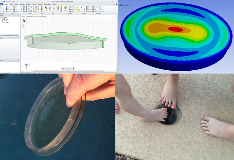
- Recognize a need
- Design a solution
- Verify the solution
- Manufacture the solution
- Deploy the solution
There are other steps that could be added such as optimization and field verification, but in simple terms those steps outline the product development process. We do this very often at PADT, helping a wide variety of customers develop products to meet needs in the marketplace. Most of the time, we can’t share the work we do publicly, for obvious reasons involving customer confidentiality.
So, when we can share, it’s a good opportunity to show what our tools can do, as well as how we can utilize these tools to help our customers with the steps listed above. We’ll look at a simple example, knowing that the same tools can help with much more complex problems.
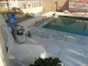
In my case, I was faced with a problem. We recently had our back yard pool deck resurfaced. The problem at hand was the contractors accidently lost a plastic lid that covered a 5.5 in. hold on the deck of the pool. This hole was for something like a basketball hoop that could be dropped into this trumpet shaped hole. Figure 1 shows the work in progress, when the original lid was still in place.
After the cleanup was done, that lid was nowhere to be found. You would think it would be simple to find a replacement, especially in metro Phoenix where pool supply stores are abundant. However, after visiting several supply stores as well as scouring the internet, we could not find a replacement 5.5 in. lid. All the available lids were too big and would not work in covering this hole. The hole without a lid is a safety concern. In fact, our 4 year old niece managed drop a foot into the hole and ended up with a scrape. Fortunately it wasn’t any worse than that.
Unable to find a suitable lid for purchase, I decided to pursue a 3D printed solution here at PADT. As I’m sure you are aware, 3D printing has been portrayed all over the media in the last couple of years. For us here at PADT, though, it has been a significant component of our business since the company’s founding in 1994. Knowing that I could have this part printed in plastic here at PADT, I decided to go through the product development process as listed above.
So, let’s look at the various steps I followed in our product development process:
- Recognize a need.
In this case, it was simple. We had a hole in the pool deck that was a safety issue. No replacement part could be found. A new lid was needed, one that would fit properly but also could support the weight of someone walking over it. I decided to design a replacement part that could be 3D printed by one of the rapid prototyping technologies we have available here at PADT.
- Design a solution
Besides providing 3D printing services and selling 3D printers, we at PADT are a Channel Partner for ANSYS engineering simulation tools here in the Southwest. I leveraged ANSYS, Inc.’s latest acquisition, the SpaceClaim Direct Modeler as my design tool. SpaceClaim has been available as part of the ANSYS software suite for several years, but now SpaceClaim is officially part of the ANSYS corporate umbrella. SpaceClaim runs within the ANSYS Workbench platform, like the ‘older’ ANSYS geometry tool, DesignModeler. A main different between the two geometry toolsets is that DesignModeler is a history-based modeler, meaning it has a history tree that is followed to create and modify the geometry as we go along. This works well in many circumstances but it lacks the ability to quickly and easily modify existing geometry. SpaceClaim, on the other hand, is a direct modeler in the sense that we work on the geometry interactively, allowing us to rapidly modify geometry by ‘pulling’ on surfaces to grow, shrink, fillet, etc. SpaceClaim is incredibly fast once we get familiar with it.
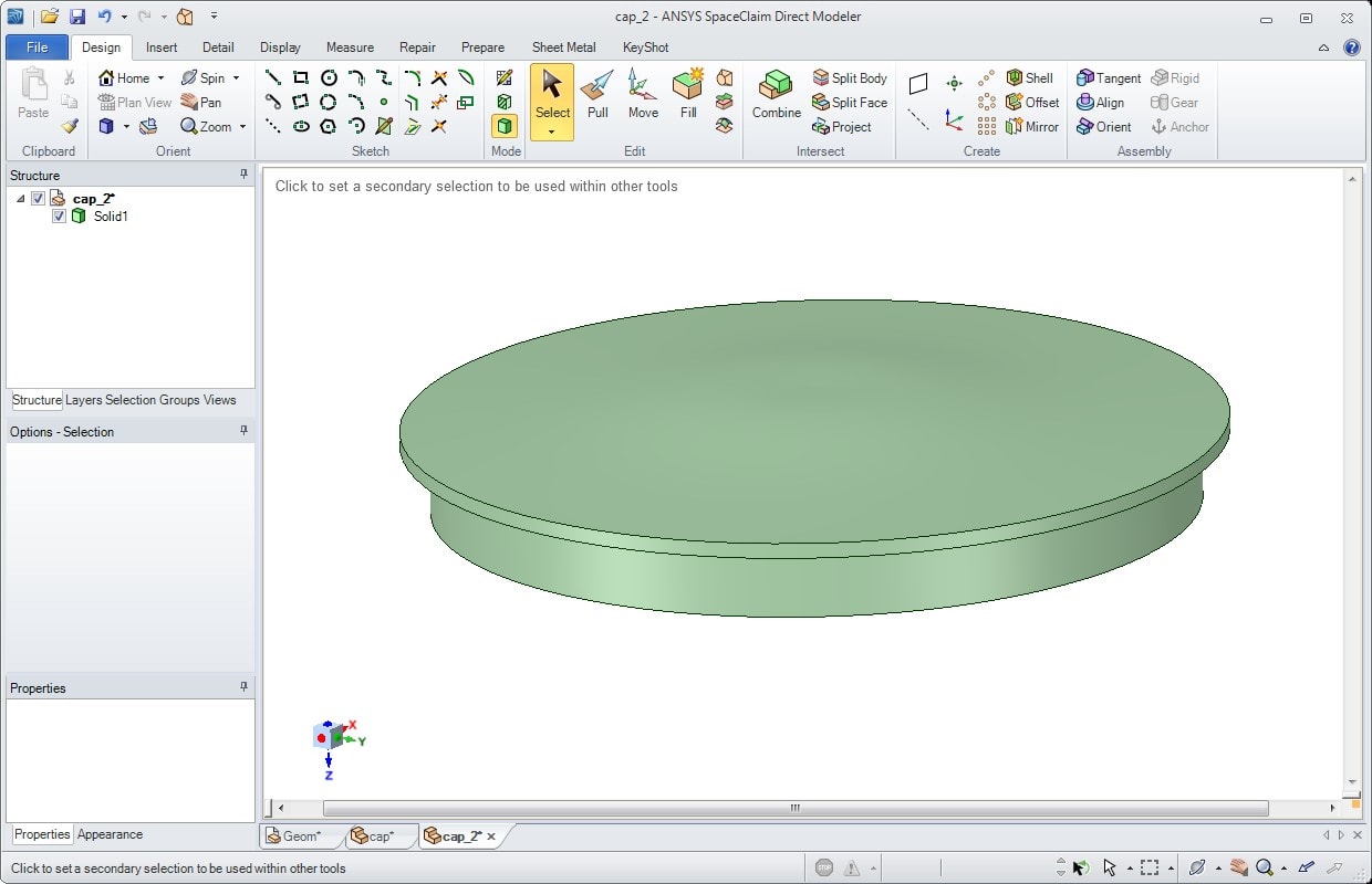
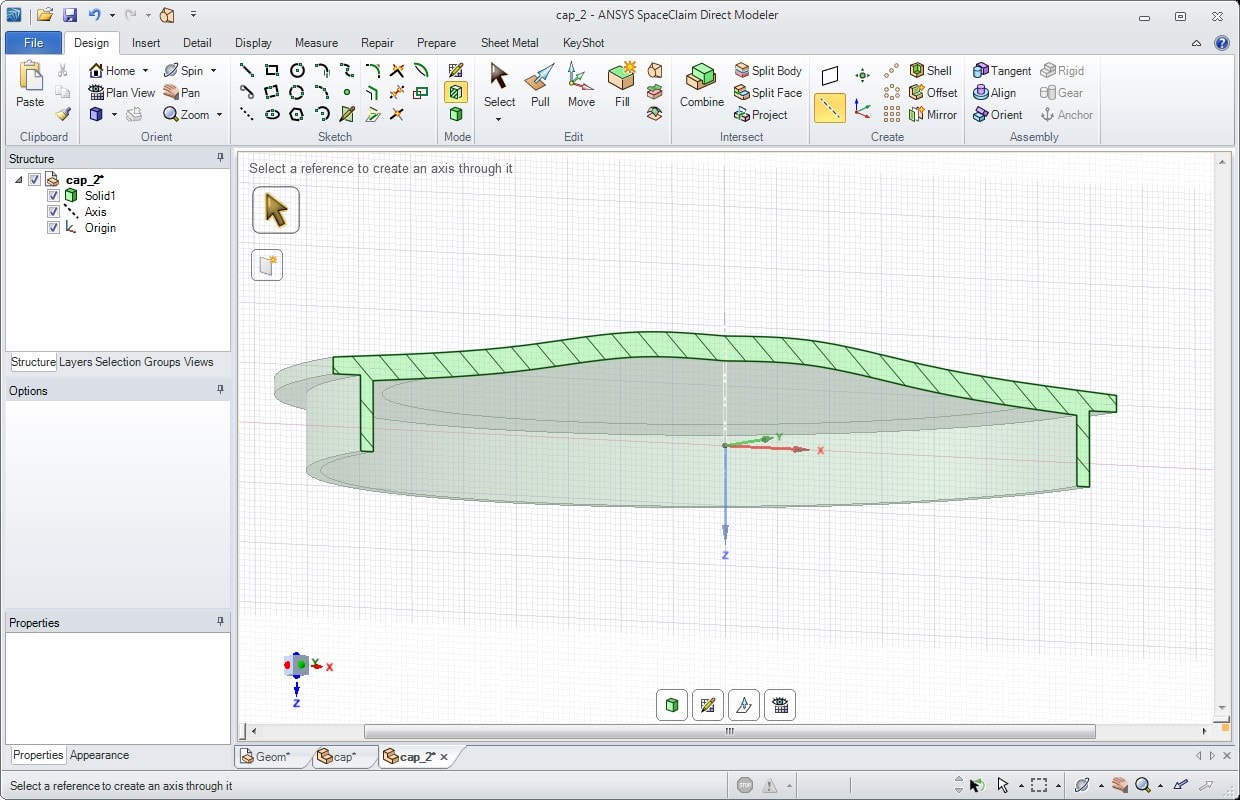
Knowing that the diameter of the hole was 5.5 inches as measured by a ruler, along with a memory of what the prior cover looked like, I turned to ANSYS SpaceClaim to come up with the geometry model. I sketched a 2D axisymmetric cross section and swept that 360 degrees about an axis to come up with the solid model. I very easily moved the 5.5 in diameter face inward by a small amount to allow for some clearance between the plastic part and the hole into which it needs to fit. The geometry definition literally took just a few minutes, even though I am not yet an expert in SpaceClaim.
- Verify the solution
I mentioned optimization as a step that could be followed. In this simple case, I didn’t do any optimization but did perform verification that my design would meet an acceptability requirement. I wanted to make sure that my plastic lid could support the weight of an adult standing on it. The tool I used to perform this verification was the ANSYS Mechanical software tool. Like SpaceClaim can, ANSYS Mechanical runs within the ANSYS Workbench environment, meaning that the geometry and subsequent stress and deflection analyses are linked. This allows any needed changes to the geometry to quickly and easily pass from the geometry tool to the stress/deflection model, often with as little as one click of the mouse.
Getting the geometry into the Mechanical model for a finite element simulation was therefore quite simple. Defining loads and constraints on my system was also quite simple. What remained was to define material properties to characterize the plastic being used. PADT’s Rapid Prototyping team informed me that the material to be used is one called Veroclear. This material is used in one of PADT’s 3D printers, called an Objet from Statasys.
Basic material properties for Veroclear are available on the internet, including Young’s Modulus and Yield Strength. Poisson’s Ratio was not available so it was assumed to be 0.3. These properties were entered into ANSYS Workbench. For those not familiar, Young’s Modulus is a quantification of the stiffness of a material. The Yield Strength is a measure of the how much stress a material can experience before permanent deformation occurs. Stress, simply put, is the amount of force being carried per area in a structure. Poisson’s Ratio relates how much a material squishes in one direction when it’s pulled in another dimension.
The loading consisted of a 210 lb. downward load on a portion of the upper surface, representing someone standing on the middle of the lid. The constraints were frictionless supports on the outer cylindrical face as well as the bottom lip. These constraints simulate where these two surfaces touch the hard surface of the pool deck.
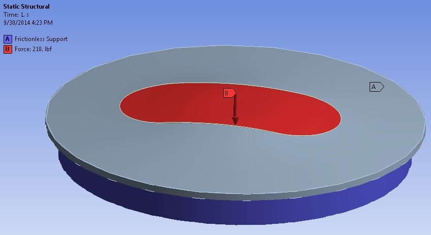
Once the model was fully setup in ANSYS Mechanical, the solution was obtained. Lots of matrix algebra behind the scenes takes care of solving the equations needed to obtain the solution. The resulting deflections and stresses looked to be acceptable. I also calculated a factor of safety, relating the calculated stress in the model to the Yield Strength as described above. A factor of safety of 2, for example, means that the predicted stress in the model is half of the Yield Strength. The calculated factor of safety for the plastic lid is 3.17.
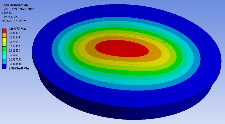
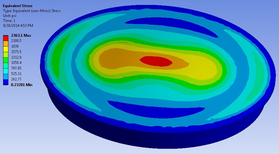
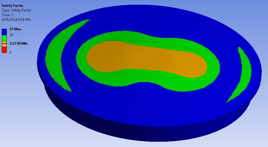
From these results we can conclude that, for the loading condition we considered:
- The deflections are fairly minimal
- The stresses are below the Yield Stress
- The minimum factor of safety value of 3.17 gives us confidence that under reasonable loadings, the part will not fail.
Note that this is a simplistic look at the feasibility of our design. We didn’t consider what happens to the plastic in the hot sun, what happens if something heavy falls on the lid, etc. Many other factors could be considered, but in this case I chose to keep it simple.
- Manufacture the solution
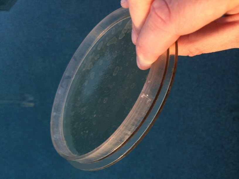
The part was printed over a weekend in an Objet printer here at PADT. The geometry was saved as a Parasolid file in ANSYS SpaceClaim, and the Parasolid file was then provided to PADT’s Rapid Prototyping team, via the rp@padtinc.com email. While the cost of making this particular plastic part using 3D printing is likely too high for a production run, the technology is perfect for making test articles, prototypes, molds, etc.
- Deploy the solution
In this case I only needed one lid, so I took care to make sure that the geometry was accurate before the CAD definition was sent to the 3D printer. The proof is always in the pudding, so to speak, so it was a great comfort to see that the new plastic lid fit perfectly in the hole in the pool deck. If this were a production part, we would probably need a vendor to mold the plastic lids in large batches to make them cost effective.
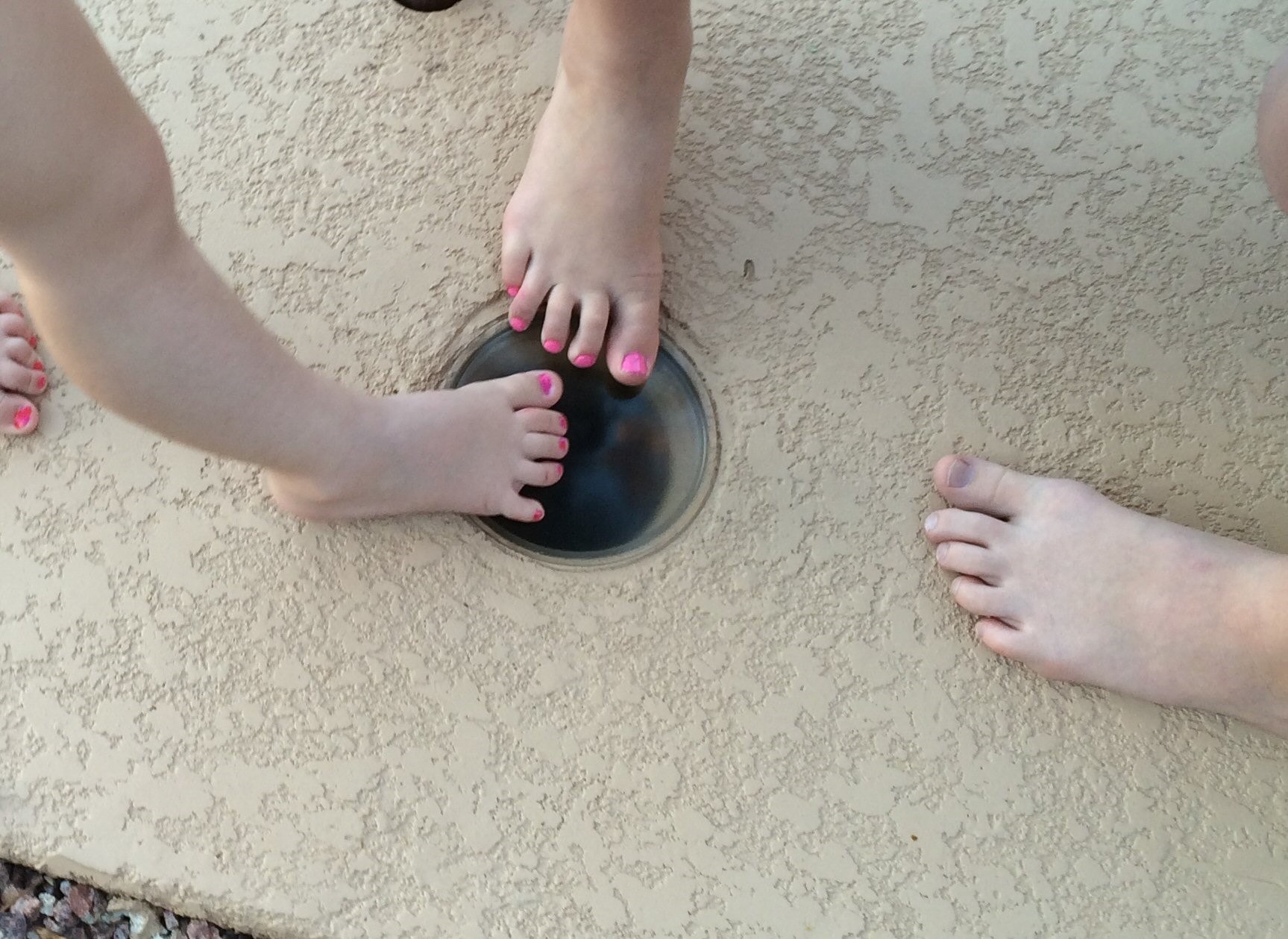
So, we ended up with a part the met the need, each step done very quickly using the appropriate tools in conjunction with the knowledge of how to use them. We hope you have enjoyed this tour of the product design process, for this simple example. Please keep PADT in mind for your product development needs.


