Nothing like a good ‘ol fashion Simpson’s reference. I’m trying to start a new series of articles that address common mistakes and things to avoid, and what better reference than when Bart ‘joined’ the Junior Campers and found out he might get a knife out of the deal.
For this first article, let’s talk about remote objects (force, displacement, points, joints). First, remote objects are awesome. Want to add a rotational DOF to your solid-object model? Remote Displacement. Want to apply a load and don’t want to worry about force/moment balance? Remote Force. Want to apply a load but also constrain a surface? Remote Point. Take two points and define a open/locked degrees of freedom and you have a kinematic joint.
The thing to watch out for is how you define these remote points. ANSYS Mechanical does an amazing job at making a pretty tedious process easy (create pilot node, create constraint-type contact, specify DOFs to include, specify formulation). In Mechanical, all you need to do is highlight some geometry, right mouse click, and insert the appropriate object (remote point, remote force, etc). No need to keep track of real constant sets, element tshape’s…easy. Almost too easy if you ask me.
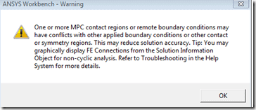
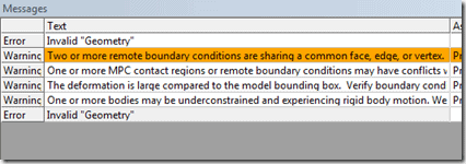
Once you start creating multiple remote objects, you may see the following:
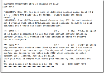
If you dig into the solver output file you may see this:
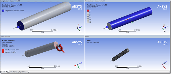
The complaint is that we have multiple overlapping constraint sets. Let’s take a step back and see the model I’ve setup:
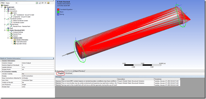
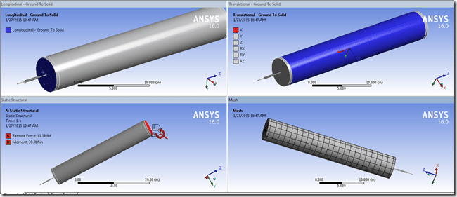
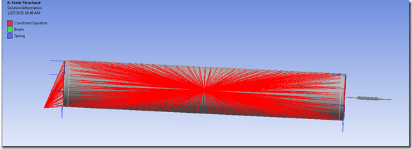
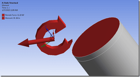
I have a cylinder, attached to a body-to-ground spring on one face, a translational joint applied on the OD, and a remote force and moment applied on the opposite end. If I follow the instructions shown from the ANSYS Workbench message about graphically displaying FE Connections (select the ‘Solution Information’ item, click the graphics tab):
We can see that any type of constraint equation is shown in red. The issue here is that the nodes on the OD edge on the top and bottom of my cylinder belong to multiple constraint equation sets. On the bottom my my cylinder those nodes are being constrained to the spring end AND the cylindrical joint. On the top the nodes on the edge are being constrained to the joint AND remote force. When you hit solve, ANSYS needs to figure out how to resolve the conflicting constraint sets (a node cannot be a slave term for two different constraint sets). I don’t know exactly how the solver manages this, but I like to imagine it’s like two people fighting over who gets to keep a dog…and they place the dog in-between them and call for it, and whoever the dog goes to gets to keep it.
Now for this example, the solver is capable of handling the over-constraint because overall…the model is properly constrained. The spring can loose some of the edge nodes and still properly connect to the cylinder. Same goes for the other remote objects (translation joint and remote force/moment). If we had more objects defined and more overlaps, that’s a different story. You can introduce a pretty lengthy lag, or outright solver failure, if there are a lot of overconstraint terms in the model.
So now the question becomes, how do I fix this. The easiest way is to not fix this and ignore the warning. If our part behaves properly, we get the reaction forces we’d expect, then odds are the overconstraint terms that are automatically corrected are fine. If we actually wanted to remove that warning, we would need to make sure we scope remote objects that do not touch other remote objects. We can do this by going into DesignModeler or SpaceClaim and imprinting the surfaces.
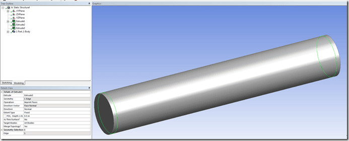
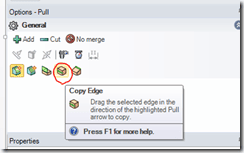
In DM, I just extruded the edges with the operation set to imprint face. In SpaceClaim you would just need to use the ‘copy edge’ option on the pull command:
Now this will modify the topology and will ensure we have a separation of nodes for all of our remote objects:
When we solve…no warning message about MPC conflicts:
And when we look at the FE connectivity, there are no nodes shared by multiple remote objects:
The last thing I’d like to point out is the application of a force and moment on a remote point:
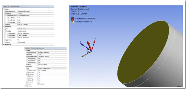
Whenever you have two remote objects operating on the same surface (e.g. a moment and force, force and displacement, etc), you should really be using a remote point. If I were to create two remote objects:
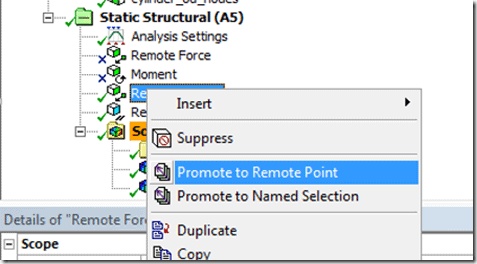
I now come right back to my original problem of conflicting constraints. These two objects share the exact same nodal set but are creating two independent remote points. If you want to do this, right-mouse-click on one of your remote objects and select ‘promote to remote point’:
Then modify the other remote objects to use that remote point. No more conflict.
Very last point…in R16 it will now tell you when you have ‘duplicate’ remote objects (like the remote force + displacement shown above).
Hope this helps!

