Here is an example of this new procedure. (Note that we don’t have NASTRAN here at PADT, so I couldn’t create a generic sample of a NASTRAN model in NASTRAN. Instead, I created a model in ANSYS, then converted it into NASTRAN using ANSYS FE Modeler to get a NASTRAN input file for the purpose of this exercise.)
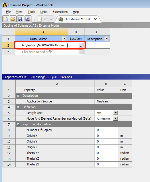
Once I have the NASTRAN input file that I need to convert into ANSYS Mechanical, I launch ANSYS Workbench 16.0 and insert an External Model branch. I then click the … button to browse to the NASTRAN input file. In this case, the file is NASTRAN.nas.
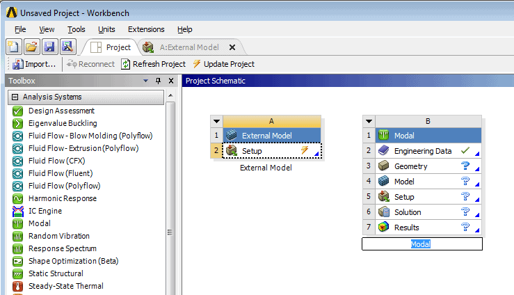
Next, I drag and drop a new analysis type block into the Project Schematic. In this case, it was a modal analysis. Note that you can’t drop this onto the Setup cell in the External Model block as you might expect. You set it up as a separate block and establish the link in the next step.
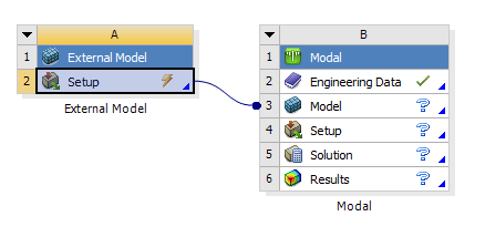
Next, we drag and drop the Setup cell from the External Model block onto the Model cell of the Modal analysis block. This establishes the link from the NASTRAN model to the new Modal analysis.
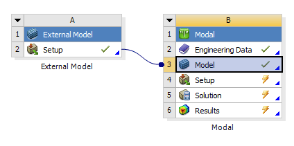
We also need to right click on the Setup cell in the External Model block and select Update to get a green checkmark in that cell:
Notice that there is no Geometry cell in the resulting Modal analysis block. If all goes well, there will be geometry within the Mechanical model that can be used for selection purposes (in addition to the mesh that comes in from NASTRAN).
Next we open the Mechanical editor by double clicking on one of the cells in the Modal analysis blocks (other than the Engineering Data cell). It may take several minutes to bring in the NASTRAN model depending on the size of the NASTRAN model. The Mechanical window doesn’t really let you know that it’s working, but if it’s sitting there with nothing being displayed, it’s probably churning away at bringing in the NASTRAN mesh and creating surface geometry on it.
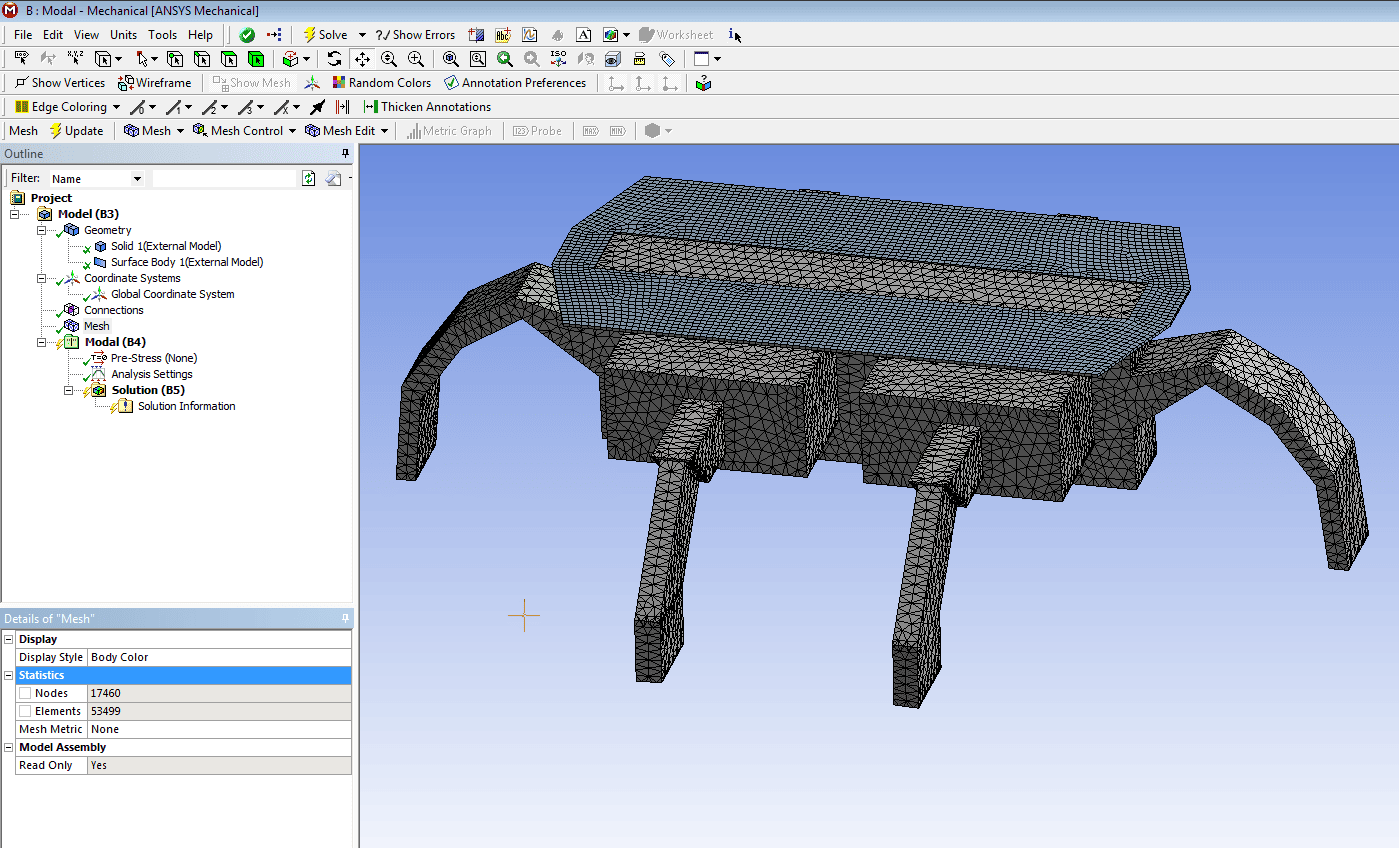
Here is what the Mechanical window looks like after the mesh is read in and geometry is automatically created. This is the mesh from the NASTRAN file, but in this case both solid and surface geometry is also present. It’s not guaranteed that everything will come across. I’ve seen contact elements come through for certain types of contact but not for other types of contact for example.
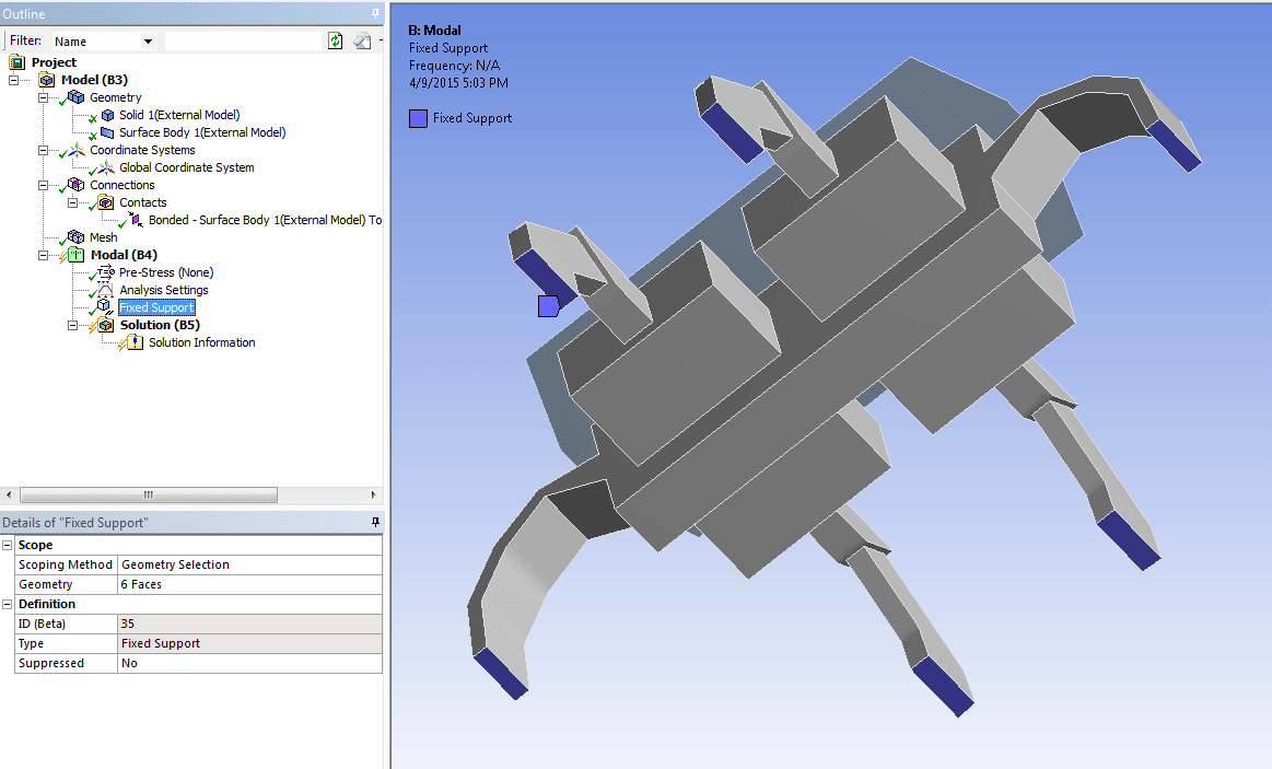
The next image shows that geometry was created that can be used for the purposes of inserting fixed supports, just as if the geometry had come in from a CAD system. Note that the NASTRAN input file had NO geometry, just finite element entities. ANSYS is creating the geometry for use in Mechanical from the information in the NASTRAN input file.
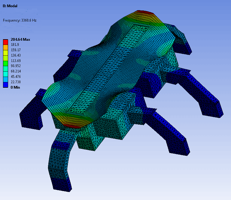
Finally, after manually creating a needed contact region, I was able to solve the modal analysis, demonstrating that further simulation can be performed in ANSYS Mechanical from this model which originally came from NASTRAN.
So, the main take away here is that with version 16.0 of ANSYS, we can take a NASTRAN input file and through the use of the External Model block, go directly into ANSYS Mechanical. Not only do we get the nodes and elements as well as other finite element entities from the NASTRAN model, but if all goes well we get geometry that facilitates further processing within ANSYS Mechanical.
We certainly hope this new capability makes it easier for you to perform additional simulations in ANSYS when the starting point is a NASTRAN model. The other formats documented for version 16.0 are ABAQUS, Fluent input files, and ICEM CFD input files.

