Be a Pinball Wizard with Contact Regions in ANSYS Mechanical

Categories:
pinball-wizard-pinball-machine-ANSYS-3
A pinball machine based on The Who’s Tommy

I had a very cool music teacher back in 6th or 7th grade in the 1970’s in upstate New York.  Today we’d probably say she was eclectic.  In that class we listened to and discussed fairly recent songs in addition to general music studies.  Two songs I remember in particular are ‘Hurdy Gurdy Man’ by Donovan and ‘Pinball Wizard’ by The Who.  If you’re not familiar with Pinball Wizard, it’s from The Who’s rock opera Tommy, and is about a deaf, mute, blind young man who happens to be adept at the game of pinball.  Yes, he is a Pinball Wizard.  This sing popped into my head recently when we had some customer questions here at PADT regarding the pinball region concept as it pertains to ANSYS contact regions.

I’m not sure if the developers at ANSYS, Inc. had this song in mind when they came up with the nomenclature for the 17X (latest and greatest) series of contact elements in ANSYS, but regardless, you too can be a pinball wizard when it comes to understanding contact elements in ANSYS Mechanical and MAPDL.

Fans of this blog may remember one of my prior posts on contact regions in ANSYS that also had a musical theme (bringing to mind Peter Gabriel’s song “I Have the Touch”):

In this current entry we will go more in depth on the pinball region, also known as the pinball radius.  The pinball region is involved with the distance from contact element to target element in a given contact region.  Outside the pinball region, ANSYS doesn’t bother to check to see if the elements on opposite sides of the contact region are touching or not.  The program assumes they are far away from each other and doesn’t worry about any additional calculations for the most part.

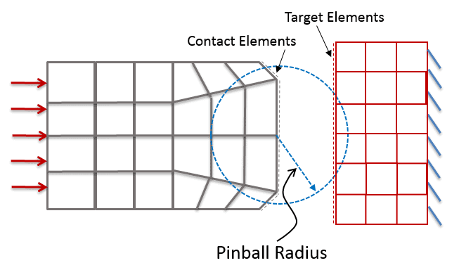
Here is an illustration.  The gray elements on the left represent the contact body and the red elements on the right represent the target body (assuming asymmetric contact).  Target elements outside the pinball radius will not be checked for contact.  The contact and target elements actually ‘coat’ the underlying solid elements so they are shown as dashed lines slightly offset from the solid elements for the sake of visibility.  Here the pinball radius is displayed as a dashed blue circle, centered on the contact elements, with a radius of 2X the depth of the underlying solid elements.

pinball_radius_contact_illustration

So, outside the pinball region, we know ANSYS doesn’t check to see if the contact and target are actually in contact.  It just assumes they are far away and not in contact.  What about what happens if the contact and target are inside the pinball region?  The answer to that question depends on which contact type we have selected.

For frictionless contact (aka standard contact in MAPDL) and frictional contact, the program will then check to see if the contact and target are truly touching.  If they are touching, the program will check to see if they are sliding or possibly separating.  If they are touching and penetrating, the program will check to see if the penetration exceeds the allowable amount and will make adjustments, etc.  In other words, for frictionless and frictional contact, if the contact and target elements are close enough to be inside the pinball region, the program will make all sorts of checks and adjustments to make sure the contact behavior is adequately captured.

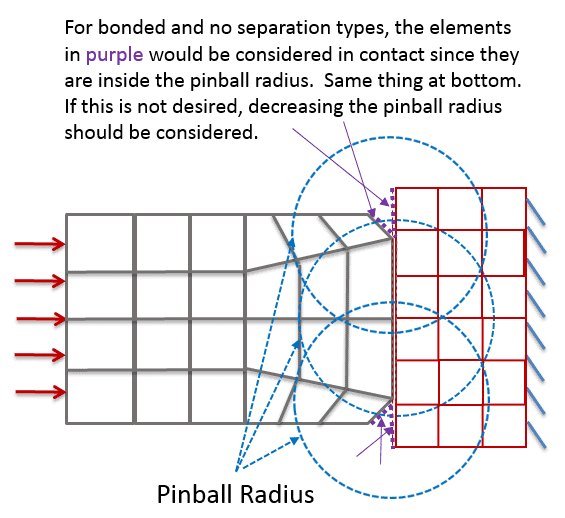
The other scenario is for bonded and no separation contact.  With these contact types, the program’s behavior when the contact and target elements are within the pinball region is different.  For these types, as long as the contact and target are close enough to be within the pinball region, the program considers the contact region to be closed.  So, for bonded and no separation, your contact and target elements do not need to be line on line touching in order for contact to be recognized.  The contact and target pairs just need to be inside the pinball region.  This can be good, in that it allows for some ‘slop’ in the geometry to be automatically ignored, but it also can have a downside if we have a curved surface touching a flat surface for example.  In that case, more of the curved surface may be considered in contact than would be the case if the pinball region was smaller.  This effect is shown in the image below.  Reducing the pinball radius to an appropriate smaller amount would be the fix for eliminating this ‘overconstraint’ if desired.

pinball_radius_bonded_noseparation

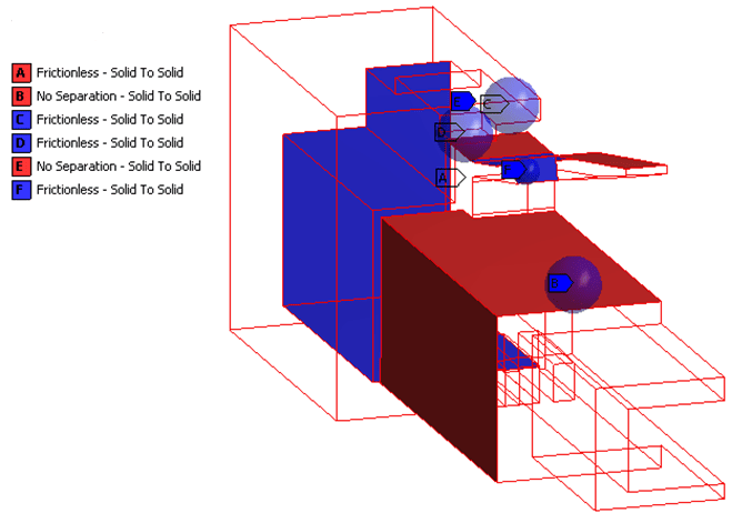
There is a default value for the pinball region/radius.  It can be changed if needed.  We’ll add more details in a moment.  First, why is it called the “pinball” region?  I like to think it’s because when it’s visualized in the Mechanical window, it looks like a blue pinball from an actual pinball arcade game, but I’ll admit that the ANSYS terminology may predate the Mechanical interface.  The image below shows what I mean.  The blue balls are the different pinball radii for different contact regions.

pinball_radius_visualization


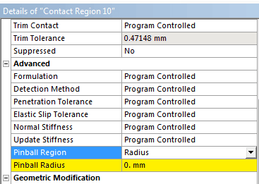
Note that you don’t see the pinball region displayed as shown in the above image unless you have manually changed the pinball size in Mechanical.  The pinball region can be changed in the Mechanical window in the details view for each contact region by changing Pinball Region from Program Controlled to Radius, like this:

pinball_radius_change

In MAPDL, the pinball radius value can be changed by defining or editing the real constant labeled PINB.

By now you’re probably wondering what is the default value for the pinball radius?  The good news is that it is intelligently decided by the program for each contact region.  The default is always a scale factor on the depth of the underlying elements of each contact region.  In the first pinball region image shown near the beginning of this article, the example plot shows the pinball region/radius as two times the depth of the underlying elements.

The table below summarizes the default pinball radius values for most circumstances for 2D and 3D solid element models.  More detailed information is available in the ANSYS Help.

[table id=2 /]

Summing it all up:  we have seen how the default values are calculated and also how to change them.  We have seen what they look like as blue balls in a plot of contact regions in Mechanical if the pinball radius has been explicitly defined.  We also discussed what the pinball radius does and how it’s different for frictionless/frictional contact and bonded/no separation contact.

You should be well on your way to becoming a pinball wizard at this point.

Does performing simulation in ANSYS make you think of certain songs, or are there songs you like to listen to while working away on your simulations an addition to The Who’s “Pinball Wizard” and Peter Gabriel’s “I Have the Touch”?  If so, we’d love to hear about your song preferences in the comments below.

Categories

Get Your Ansys Products & Support from the Engineers who Contribute to this Blog.

Technical Expertise to Enable your Addictive Manufacturing Success.

PADT Pulse Newsletter Screen Grab from March 2023

PADT’s Pulse Newsletter

Keep up to date on what is going on at PADT by subscribing to our newsletter.


By submitting this form, you are consenting to receive marketing emails from: . You can revoke your consent to receive emails at any time by using the SafeUnsubscribe® link, found at the bottom of every email. Emails are serviced by Constant Contact

Share this post:

Upcoming Events

05/31/2023

Driving Automotive Innovation with Additive - Webinar

05/24/2023

Hill Air Force Base Tech Expo

05/24/2023

Structural Updates in Ansys 2023 R1 (3) – Structural Optimization & Ex

05/23/2023

CROSSTALK 2023: Emerging Opportunities for Advanced Manufacturing Smal

05/10/2023

Signal & Power Integrity Updates in Ansys 2023 R1 - Webinar

04/26/2023

Additive Manufacturing Updates in Ansys 2023 R1 - Webinar

04/20/2023

38th Space Symposium Arizona Space Industry

More Info

04/19/2023

38th Space Symposium
Arizona Space Industry

04/19/2023

Additive Aids for Manufacturing - Webinar

04/18/2023

38th Space Symposium
Arizona Space Industry

04/17/2023

38th Space Symposium

04/13/2023

Venture Madness 2023

04/12/2023

Fluid Meshing & GPU-Solver Updates in Ansys 2023 R1 - Webinar

03/29/2023

8th Thermal and Fluids Engineering Conference

03/29/2023

Structural Updates in Ansys 2023 R1 - Composites, Fracture & MAPDL

03/28/2023

8th Thermal and Fluids Engineering Conference

03/27/2023

8th Thermal and Fluids Engineering Conference

03/26/2023

8TH Thermal and Fluids Engineering Conference

03/24/2023

Arizona BioPreneur Conference | Spring 2023

03/22/2023

2023 Arizona MedTech Conference

03/22/2023

Optimize Jigs & Fixtures with Additive - Webinar

03/15/2023

3D Design Updates in Ansys 2023 R1 - Webinar

03/08/2023

Competitive Advantages of 1D/3D Coupled Simulation - Webinar

03/01/2023

High Frequency Updates in Ansys 2023 R1 - Webinar

02/22/2023

Additive Advantages in Aerospace - Webinar

02/15/2023

Structural Updates in Ansys 2023 R1 (1) - Webinar

02/09/2023

IME 2023: MD&M | WestPack | ATX | D&M | Plastek

02/08/2023

IME 2023 MD&M | WestPack | ATX | D&M | Plastek

02/07/2023

IME 2023 MD&M | WestPack | ATX | D&M | Plastek

01/27/2023

Arizona Photonics Days, 2023

01/26/2023

Arizona Photonics Days, 2023

01/26/2023

TIPE 3D Printing | 2023

01/26/2023

Venture Cafe Phoenix Talent Night - Job Fari

01/26/2023

VFS 2023 Autonomous/Electric VTOL Symposium

01/25/2023

Arizona Photonics Days, 2023

01/25/2023

Building A.M.- Utah: Kickoff!

01/25/2023

TIPE 3D Printing | 2023

01/25/2023

VFS 2023 Autonomous/Electric VTOL Symposium

01/24/2023

VFS 2023 Autonomous/Electric VTOL Symposium

01/24/2023

TIPE 3D Printing | 2023

01/18/2023

2023 AZ Tech Council Golf Tournament

12/21/2022

Simulation Best Practices for 5G Technology - Webinar

12/14/2022

Digital Twins Updates in Ansys 2022 R2 - Webinar

12/08/2022

Tech the Halls - AZ Tech Council Holiday Mixer

12/07/2022

Electric Vehicle and Other Infrastructure Update Panel

11/30/2022

SPEOS Updates in Ansys 2022 R2 - Webinar

11/23/2022

Simulation Best Practices for Electronics Reliability - Webinar

11/16/2022

Discovery Updates in Ansys 2022 R2

11/10/2022

VentureCafe Phoenix Panel: Venture Capital in AZ

11/08/2022

2022 GOVERNOR’S CELEBRATION OF INNOVATION AWARDS + TECH SHOWCASE

11/03/2022

VentureCafe Phoenix Panel: Angel Investment in AZ

11/02/2022

High & Low Frequency Electromagnetics Updates in Ansys 2022 R2

10/26/2022

Simulation Best Practices For Chip-Package-System Design & Development

10/20/2022

Nerdtoberfest 2022

10/19/2022

2022 Southern Arizona Tech + Business Expo

10/19/2022

LS-DYNA Updates in Ansys 2022 R2 - Webinar

10/17/2022

Experience Stratasys Truck Tour - Clearfield Utah

10/14/2022

ASU School of Manufacturing Systems and Networks - Formal Opening Cele

10/14/2022

Experience Stratasys Truck Tour - Midvale Utah

10/12/2022

Experience Stratasys Truck Tour - Littleton Colorado

10/06/2022

Fluids Updates in Ansys 2022 R2 - Webinar

10/05/2022

Experience Stratasys Truck Tour - Colorado Springs

09/29/2022

White Hat Life Science Investor Conference - 2022

09/28/2022

2022 AZBio Awards

09/28/2022

Simulation Best Practices for Rotating Machinery Design & Development

09/21/2022

ExperienceIT NM 2022

09/21/2022

Additive Updates in Ansys 2022 R2 - Webinar

09/14/2022

Rocky Mountain Life Sciences Investor & Partnering Conference

09/08/2022

Ansys Optics Simulation User Group Meeting - Virtual

09/08/2022

Ansys Optics Simulation User Group Meeting

09/07/2022

SI & PI Updates in Ansys 2022 R2 - Webinar

08/31/2022

Simulation Best Practices for Developing Medical Devices - Webinar

08/24/2022

Mechanical Updates in Ansys 2022 R2 - Webinar

08/10/2022

Tucson after5 Tech Mixer: Ruda-Cardinal

08/05/2022

Flagstaff Tech Tour, 2022

08/02/2022

2022 CEO Leadership Retreat

08/01/2022

2022 CEO Leadership Retreat

07/27/2022

Thermal Integrity Updates in Ansys 2022 R1 - Webinar

07/20/2022

Simulation Best Practices for the Pharmaceutical Industry - Webinar

07/14/2022

NCMS Technology Showcase: Corpus Christi Army Depot

07/13/2022

NCMS Technology Showcase: Corpus Christi Army Depot

07/13/2022

Additive & Structural Optimization Updates in Ansys 2022 R1 - Webinar

07/07/2022

Arizona AADM Conference, 2022

06/29/2022

LS-DYNA Updates & Advancements in Ansys 2022 R1 - Webinar

06/23/2022

Simulation Best Practices for Wind Turbine Design - Webinar

06/15/2022

MAPDL Updates & Advancements in Ansys 2022 R1 - Webinar

06/01/2022

Mechanical Updates in Ansys 2022 R1 - pt. 2 Webinar

05/26/2022

Modelling liquid cryogenic rocket engines in Flownex - Webinar

05/25/2022

SMR & Advanced Reactor 2022

05/25/2022

05/24/2022

SMR & Advanced Reactor 2022

05/19/2022

RAPID + tct 2022

05/19/2022

Venture Cafe Roundtable: AI & Healthcare

05/18/2022

Tucson after5 Tech Mixer: World View

05/18/2022

RAPID + tct 2022

More Info

05/18/2022

Signal & Power Integrity Updates in Ansys 2022 R1 - Webinar

05/18/2022

Simulation World 2022

05/17/2022

RAPID + tct 2022

05/11/2022

Experience Stratasys Manufacturing Virtual Event

Search in PADT site

Contact Us

Most of our customers receive their support over the phone or via email. Customers who are close by can also set up a face-to-face appointment with one of our engineers.

For most locations, simply contact us: