Support Design and Removal for 3D Printed ULTEM-9085 (Case Study: Intake Manifold)

Editor’s note: Unfortunately this post and a few others were the victim of database munging that resulted in the images being lost. We are trying to recover them. We hope that you find the text useful even without the images. 

ULTEM-9085 is one of my favorite materials to 3D-print: one of the reasons is it is a high performance polymer that can and has been used for end part manufacturing (see my blog post about ULTEM in functional aerospace parts), but the other is because it is a demanding material to print, in ways that ABS, Polycarbonate and even Nylon are not. What makes it demanding is primarily that ULTEM supports are not soluble and need to be removed mechanically. An additional challenge comes from the fact that the support is best removed when the part is at a high temperature (175-195 C), which requires the use of gloves and reduces the user’s dexterity. For complex geometries with internal channels, this is particularly challenging and occasionally results in an inability to print a certain part in ULTEM-9085, which runs contrary to the design freedom this technology otherwise enables.

In this post, I accumulate what I have learned through working (and failing) on many an ULTEM-9085 job, as well as through discussions with other users, and share this here in terms of design and process guidelines. To demonstrate these guidelines, I use a recent geometry that we printed for the Arizona State University’s (ASU) SAE team for an engine intake manifold. These guidelines apply to the Stratasys Fortus platform (for Fused Deposition Modeling, or FDM) using the Insight software that accompanies these tools. The screen shots are from Insight 10.6, and a Fortus 400 was used to print the parts shown.

Summary of Guidelines:

  1. Orient the part to eliminate supports in regions where you cannot remove them
  2. Use the box support style
  3. Optimize parameter settings (support angle, contour width, layer thickness)
  4. Remove the supports as soon as the part comes out of the build chamber
  5. Other observations: the interface of separation

1. Part Orientation

The single most important factor in simplifying support removal is part orientation. Most users of the FDM process know that part orientation determines the amount of support material consumed and also impacts the time to build the part. When working with ULTEM-9085, the additional challenge is that it is possible to design in supports that cannot be removed and will require you to scrap the job. This is especially true of internal features. While the automatic orientation feature in Insight allows you to minimize supports, it does not account for the difficulty of removing them. Thus when you are dealing with internal features, you may need to manually orient your part such that the internal features are aligned as close to the vertical as possible, and above the support angle (to be covered later).

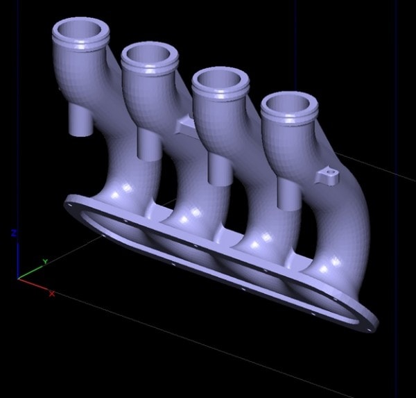
As shown in Figure 1, for the intake manifold, I oriented the internal pipe structure close to the vertical and had to iterate a few times and verify that I had no support in the hard-to-reach areas. While I did have supports internally, they were limited to areas that were easy to access.

Figure 1. Engine intake manifold, to be printed out of ULTEM-9085
Figure 2. Part orientation to avoid any internal supports
Figure 2. Part orientation to avoid any internal supports in inaccessible regions

2. Box Supports

In a recent software upgrade, Insight added the ability to create box supports. The support structures consist of adjacent boxes instead of a continuous raster, which has the effect of allowing for easier separation of the support, though does slow down the build time. In my experience this support strategy does help with removal – the one parameter to consider here is the “Perforations” setting, though the default values were used for this part. The perforation is a layer of model material that is inserted into the support to make for easier breaking off of the support material. All cleavage surfaces in Fig. 3 are at perforation edges and you can see the building like construction with each floor distinguished by a layer of model material. When you have supports in hard to access regions, consider increasing the interval height so as to ensure you get separation at the model-support interface on the part before it occurs within the support on a perforation layer.

Figure Box Supports
Figure 3. Box Supports after removal from an ULTEM-9085 part

3. Optimize Process Parameters

While orientation will have the most significant impact on the support you need, another variable to be aware of is the “Self-Support Angle” parameter. This angle is measured from the horizontal, and represents the minimum angle of the part wall that will be built without supports. As a result, to reduce support requirements, you want this number to be as low as possible so that a greater volume of the part can be self-supported. Stratasys recommends default values, but these scale as a function of the contour width, and layer thickness, as shown in Fig. 4. The values bottom out at 40 degrees for the 0.013″ layer thickness and 43 degrees for the 0.010″ layer thickness. Thus, all other things being equal, you will be able to reduce the support needed by choosing a 0.013″ layer thickness and a 0.026″ or larger contour width. Note that both of these will impact your ability to resolve thin walls and fine features, so ensure you scan through all the tool-paths to validate that the geometry is accurately filled in.

angle width3
Figure 4. Graph showing how the default values of the self-support angle vary as a function of contour width for the two layer thickness options available for ULTEM. Lower the angle, less the support needed.

4. Remove Supports Immediately

Supports are best removed when the model-support interface is hot. The best time to do this is right after you remove the parts from the print chamber, which is held at 195 C for ULTEM-9085. Ensure you have safety glasses on, work with thermal gloves and have a plier handy to pull out the support. In theory the parts can be re-heated again (175 C is a reasonable value for the oven), but Stratasys suggests that each re-heat cycle actually strengthens the interface, making it harder to remove. As a result, the best time to remove the supports is immediately out of the printer. Figure 5 shows the results of support removal for the intake manifold parts, including the build sheet.

Figure 5. Support removal can be a messy affair as you beat the clock against the cooling parts. Ensure you have gloves, a plier and safety glasses on.

5. Other Observations: the Interface of Separation

It helps to visualize what we are trying to do when we remove supports. There are two interfaces in question here, as shown in Figure 6. One is the model-support interface, the other is the support-box structure interface. We need separation at the model-support interface since removing the thin piece of interface material can prove challenging if the box supports have broken off (as happened for the piece below). What this means is as you remove support, you need to not just pull the supports but also add some peeling force that creates the separation. Once you create separation at the correct interface, you can pull the supports and should have proper cleavage.

Figure 6. (top) Support-model interface surface, and (bottom) support structure interface - it is important to get separation at the former interface
Figure 6. (top) Support-model interface surface, and (bottom) support structure interface – it is important to get separation at the former interface

One final point to keep in mind is that in some cases, eliminating internal supports may be impossible, as shown for a different part in Figure 7 below. The point is to eliminate the support in places you cannot reach with your pliers and get enough peeling force applied to. In the case below, I chose to have supports at the wide opening since I had adequate access to them. With practice, you will get a better sense of what supports can and cannot be removed and use that intuition to better shape your design and process layout decisions before you print.

Figure 6. Support in internal features are alright as long as you have access to them
Figure 7. Support in internal features are alright as long as you have access to them
Figure 7. The final part!
Figure 8. The final part
The ULTEM intake manifold runner and plenum being put through its paces at the ASU Formula SAE test rig
Figure 9. The ULTEM intake manifold runner along with a plenum that we also printed, both being put through their paces at the ASU Formula SAE test rig (Photo Ack: Michael Conard)

Show your support for ASU’s Formula SAE team at their Facebook page and see a video about the endeavor here.

Categories

Get Your Ansys Products & Support from the Engineers who Contribute to this Blog.

Technical Expertise to Enable your Addictive Manufacturing Success.

PADT Pulse Newsletter Screen Grab from March 2023

PADT’s Pulse Newsletter

Keep up to date on what is going on at PADT by subscribing to our newsletter.


By submitting this form, you are consenting to receive marketing emails from: . You can revoke your consent to receive emails at any time by using the SafeUnsubscribe® link, found at the bottom of every email. Emails are serviced by Constant Contact

Share this post:

Upcoming Events

05/31/2023

Driving Automotive Innovation with Additive - Webinar

05/24/2023

Hill Air Force Base Tech Expo

05/24/2023

Structural Updates in Ansys 2023 R1 (3) – Structural Optimization & Ex

05/23/2023

CROSSTALK 2023: Emerging Opportunities for Advanced Manufacturing Smal

05/10/2023

Signal & Power Integrity Updates in Ansys 2023 R1 - Webinar

04/26/2023

Additive Manufacturing Updates in Ansys 2023 R1 - Webinar

04/20/2023

38th Space Symposium Arizona Space Industry

More Info

04/19/2023

38th Space Symposium
Arizona Space Industry

04/19/2023

Additive Aids for Manufacturing - Webinar

04/18/2023

38th Space Symposium
Arizona Space Industry

04/17/2023

38th Space Symposium

04/13/2023

Venture Madness 2023

04/12/2023

Fluid Meshing & GPU-Solver Updates in Ansys 2023 R1 - Webinar

03/29/2023

8th Thermal and Fluids Engineering Conference

03/29/2023

Structural Updates in Ansys 2023 R1 - Composites, Fracture & MAPDL

03/28/2023

8th Thermal and Fluids Engineering Conference

03/27/2023

8th Thermal and Fluids Engineering Conference

03/26/2023

8TH Thermal and Fluids Engineering Conference

03/24/2023

Arizona BioPreneur Conference | Spring 2023

03/22/2023

2023 Arizona MedTech Conference

03/22/2023

Optimize Jigs & Fixtures with Additive - Webinar

03/15/2023

3D Design Updates in Ansys 2023 R1 - Webinar

03/08/2023

Competitive Advantages of 1D/3D Coupled Simulation - Webinar

03/01/2023

High Frequency Updates in Ansys 2023 R1 - Webinar

02/22/2023

Additive Advantages in Aerospace - Webinar

02/15/2023

Structural Updates in Ansys 2023 R1 (1) - Webinar

02/09/2023

IME 2023: MD&M | WestPack | ATX | D&M | Plastek

02/08/2023

IME 2023 MD&M | WestPack | ATX | D&M | Plastek

02/07/2023

IME 2023 MD&M | WestPack | ATX | D&M | Plastek

01/27/2023

Arizona Photonics Days, 2023

01/26/2023

Arizona Photonics Days, 2023

01/26/2023

TIPE 3D Printing | 2023

01/26/2023

Venture Cafe Phoenix Talent Night - Job Fari

01/26/2023

VFS 2023 Autonomous/Electric VTOL Symposium

01/25/2023

Arizona Photonics Days, 2023

01/25/2023

Building A.M.- Utah: Kickoff!

01/25/2023

TIPE 3D Printing | 2023

01/25/2023

VFS 2023 Autonomous/Electric VTOL Symposium

01/24/2023

VFS 2023 Autonomous/Electric VTOL Symposium

01/24/2023

TIPE 3D Printing | 2023

01/18/2023

2023 AZ Tech Council Golf Tournament

12/21/2022

Simulation Best Practices for 5G Technology - Webinar

12/14/2022

Digital Twins Updates in Ansys 2022 R2 - Webinar

12/08/2022

Tech the Halls - AZ Tech Council Holiday Mixer

12/07/2022

Electric Vehicle and Other Infrastructure Update Panel

11/30/2022

SPEOS Updates in Ansys 2022 R2 - Webinar

11/23/2022

Simulation Best Practices for Electronics Reliability - Webinar

11/16/2022

Discovery Updates in Ansys 2022 R2

11/10/2022

VentureCafe Phoenix Panel: Venture Capital in AZ

11/08/2022

2022 GOVERNOR’S CELEBRATION OF INNOVATION AWARDS + TECH SHOWCASE

11/03/2022

VentureCafe Phoenix Panel: Angel Investment in AZ

11/02/2022

High & Low Frequency Electromagnetics Updates in Ansys 2022 R2

10/26/2022

Simulation Best Practices For Chip-Package-System Design & Development

10/20/2022

Nerdtoberfest 2022

10/19/2022

2022 Southern Arizona Tech + Business Expo

10/19/2022

LS-DYNA Updates in Ansys 2022 R2 - Webinar

10/17/2022

Experience Stratasys Truck Tour - Clearfield Utah

10/14/2022

ASU School of Manufacturing Systems and Networks - Formal Opening Cele

10/14/2022

Experience Stratasys Truck Tour - Midvale Utah

10/12/2022

Experience Stratasys Truck Tour - Littleton Colorado

10/06/2022

Fluids Updates in Ansys 2022 R2 - Webinar

10/05/2022

Experience Stratasys Truck Tour - Colorado Springs

09/29/2022

White Hat Life Science Investor Conference - 2022

09/28/2022

2022 AZBio Awards

09/28/2022

Simulation Best Practices for Rotating Machinery Design & Development

09/21/2022

ExperienceIT NM 2022

09/21/2022

Additive Updates in Ansys 2022 R2 - Webinar

09/14/2022

Rocky Mountain Life Sciences Investor & Partnering Conference

09/08/2022

Ansys Optics Simulation User Group Meeting - Virtual

09/08/2022

Ansys Optics Simulation User Group Meeting

09/07/2022

SI & PI Updates in Ansys 2022 R2 - Webinar

08/31/2022

Simulation Best Practices for Developing Medical Devices - Webinar

08/24/2022

Mechanical Updates in Ansys 2022 R2 - Webinar

08/10/2022

Tucson after5 Tech Mixer: Ruda-Cardinal

08/05/2022

Flagstaff Tech Tour, 2022

08/02/2022

2022 CEO Leadership Retreat

08/01/2022

2022 CEO Leadership Retreat

07/27/2022

Thermal Integrity Updates in Ansys 2022 R1 - Webinar

07/20/2022

Simulation Best Practices for the Pharmaceutical Industry - Webinar

07/14/2022

NCMS Technology Showcase: Corpus Christi Army Depot

07/13/2022

NCMS Technology Showcase: Corpus Christi Army Depot

07/13/2022

Additive & Structural Optimization Updates in Ansys 2022 R1 - Webinar

07/07/2022

Arizona AADM Conference, 2022

06/29/2022

LS-DYNA Updates & Advancements in Ansys 2022 R1 - Webinar

06/23/2022

Simulation Best Practices for Wind Turbine Design - Webinar

06/15/2022

MAPDL Updates & Advancements in Ansys 2022 R1 - Webinar

06/01/2022

Mechanical Updates in Ansys 2022 R1 - pt. 2 Webinar

05/26/2022

Modelling liquid cryogenic rocket engines in Flownex - Webinar

05/25/2022

SMR & Advanced Reactor 2022

05/25/2022

05/24/2022

SMR & Advanced Reactor 2022

05/19/2022

RAPID + tct 2022

05/19/2022

Venture Cafe Roundtable: AI & Healthcare

05/18/2022

Tucson after5 Tech Mixer: World View

05/18/2022

RAPID + tct 2022

More Info

05/18/2022

Signal & Power Integrity Updates in Ansys 2022 R1 - Webinar

05/18/2022

Simulation World 2022

05/17/2022

RAPID + tct 2022

05/11/2022

Experience Stratasys Manufacturing Virtual Event

Search in PADT site

Contact Us

Most of our customers receive their support over the phone or via email. Customers who are close by can also set up a face-to-face appointment with one of our engineers.

For most locations, simply contact us: