
In this post, I discuss six challenges that make the modeling of 3D printed cellular structures (such as honeycombs and lattices) a non-trivial matter. In a following post, I will present how some of these problems have been addressed with different approaches.
At the outset, I need to clarify that by modeling I mean the analytical representation of material behavior, primarily for use in predictive analysis (simulation). Here are some reasons why this is a challenging endeavor for 3D printed cellular solids – some of these reasons are unique to 3D printing, others are a result of aspects that are specific to cellular solids, independent of how they are manufactured. I show examples with honeycombs since that is the majority of the work we have data for, but I expect that these ideas apply to foams and lattices as well, just with varying degrees of sensitivity.
1. Complex Geometry with Non-Uniform Local Conditions
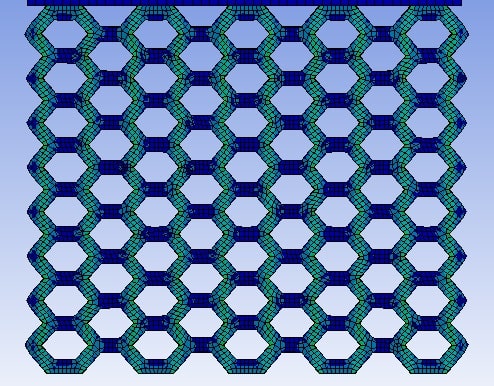
I state the most well-appreciated challenge with cellular structures first: they are NOT fully-dense solid materials that have relatively predictable responses governed by straightforward analytical expressions. Consider a dogbone-shaped specimen of solid material under tension: it’s stress-strain response can be described fairly well using continuum expressions that do not account for geometrical features beyond the size of the dogbone (area and length for stress and strain computations respectively). However, as shown in Figure 1, such is not the case for cellular structures, where local stress and strain distributions are non-uniform. Further, they may have variable distributions of bending, stretching and shear in the connecting members that constitute the structure. So the first question becomes: how does one represent such complex geometry – both analytically and numerically?

2. Size Effects
A size effect is said to be significant when an observed behavior varies as a function of the size of the sample whose response is being characterized even after normalization (dividing force by area to get stress, for example). Here I limit myself to size effects that are purely a mathematical artifact of the cellular geometry itself, independent of the manufacturing process used to make them – in other words this effect would persist even if the material in the cellular structure was a mathematically precise, homogeneous and isotropic material.
It is common in the field of cellular structure modeling to extract an “effective” property – a property that represents a homogenized behavior without explicitly modeling the cellular detail. This is an elegant concept but introduces some practical challenges in implementation – inherent in the assumption is that this property, modulus for example, is equivalent to a continuum property valid at every material point. The reality is the extraction of this property is strongly dependent on the number of cells involved in the experimental characterization process. Consider experimental work done by us at PADT, and shown in Figure 2 below, where we varied both the number of axial and longitudinal cells (see inset for definition) when testing hexagonal honeycomb samples made of ULTEM-9085 with FDM. The predicted effective modulus increases with increasing number of cells in the axial direction, but reduces (at a lower rate) for increasing number of cells in the longitudinal direction.
This is a significant challenge and deserves a full form post to do justice (and is forthcoming), but the key to remember is that testing a particular cellular structure does not suffice in the extraction of effective properties. So the second question here becomes: what is the correct specimen design for characterizing cellular properties?

3. Contact Effects
In the compression test shown in the inset in Figure 2, there is physical contact between the platen and the specimen that creates a local effect at the top and bottom that is different from the experience of the cells closer the center. This is tied to the size effect discussed above – if you have large enough cells in the axial direction, the contribution of this effect should reduce – but I have called it out as a separate effect here for two reasons: Firstly, it raises the question of how best to design the interface for the specimen: should the top and bottom cells terminate in a flat plate, or should the cells extend to the surface of contact (the latter is the case in the above image). Secondly, it raises the question of how best to model the interface, especially if one is seeking to match simulation results to experimentally observed behavior. Both these ideas are shown in Figure 3 below. This also has implications for product design – how do we characterize and model the lattice-skin interface? As such, independent of addressing size effects, there is a need to account for contact behavior in characterization, modeling and analysis.

4. Macrostructure Effects
Another consideration related to specimen design is demonstrated in an exaggerated manner in the slowed down video below, showing a specimen flying off the platens under compression – the point being that for certain dimensions of the specimen being characterized (typically very tall aspect ratios), deformation in the macrostructure can influence what is perceived as cellular behavior. In the video below, there is some induced bending on a macro-level.
5. Dimensional Errors
While all manufacturing processes introduce some error in dimensional tolerances, the error can have a very significant effect for cellular structures – a typical industrial 3D printing process has tolerances within 75 microns (0.003″) – cellular structures (micro-lattices in particular) very often are 250-750 microns in thickness, meaning the tolerances on dimensional error can be in the 10% and higher error range for thickness of these members. This was our finding when working with Fused Deposition Modeling (FDM), where on a 0.006″ thick wall we saw about a 10% larger true measurement when we scanned the samples optically, as shown in Figure 4. Such large errors in thickness can yield a significant error in measured behavior such as elastic modulus, which often goes by some power to the thickness, amplifying the error. This drives the need for some independent measurement of the manufactured cellular structure – made challenging itself by the need to penetrate the structure for internal measurements. X-ray scanning is a popular, if expensive approach. But the modeler than has the challenge of devising an average thickness for analytical calculations and furthermore, the challenge of representation of geometry in simulation software for efficient analysis.

6. Mesostructural Effects
The layerwise nature of Additive Manufacturing introduces a set of challenges that are somewhat unique to 3D Printed parts. Chief among these is the resulting sensitivity to orientation, as shown for the laser-based powder bed fusion process in Figure 5 with standard materials and parameter sets. Overhang surfaces (unsupported) tend to have down-facing surfaces with different morphology compared to up-facing ones. In the context of cellular structures, this is likely to result in different thickness effects depending on direction measured.


Summary
Modeling cellular structures has the above mentioned challenges – most have practical implications in determining what is the correct specimen design – it is our mission over the next 18 months to address some of these challenges to a satisfactory level through an America Makes grant we have been awarded. While these ideas have been explored in other manufacturing contexts, much remains to be done for the AM community, where cellular structures have a singular potential in application.
In future posts, I will discuss some of these challenges in detail and also discuss different approaches to modeling 3D printed cellular structures – they do not always address all the challenges here satisfactorily but each has its pros and cons. Until then, feel free to send us an email at info@padtinc.com citing this blog post, or connect with me on LinkedIn so you get notified whenever I write a post on this, or similar subjects in Additive Manufacturing (1-2 times/month).


