
As often happens, I learned something new from one of my latest tech support cases. I’ll start with the basics and then get to what I learned. The question in this case was, “Can I use the mode shape as a starting position for an Eigenvalue Buckling?” My first thought was, “Sure, why not,” with the idea being that the load factor would be lower if the geometry was already perturbed in that shape. Boy was I wrong.
Let’s start with the basic procedure for Eigenvalue buckling and a post-buckling analysis in ANSYS. You start with a Static Structural analysis, in this case, a simple thin column, fixed at the bottom with a 10 lbf downward force on top. Then you drag an Eigenvalue Buckling system for the toolbox, and place it on the Solution cell of the Static Structural system. After setting the number of buckling modes to search for, ANSYS calculates the Load Multiplier for each mode. If you applied the real load in the Static Structural system, then the Load Multiplier is the factor of safety with that load. If you put a dummy load, like 10lbf, then the total load that will cause buckling is F*Load Factor (l).
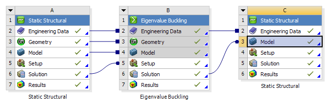
For post-buckling analysis, ANSYS 17.0 or later lets you take the mode shape from a linear Eigenvalue Buckling analysis and feed it to another Static Structural analysis Model cell as the initial geometry. We use to have to do this with the UPCOORD command in MAPDL. Now you just drag the Solution cell of the Eigenvalue Buckling analysis on to the Model cell of a stand-alone Static Structural system. Also connect the Engineering Data cells.

The key is to look at the Properties window of the Solution cell of the buckling analysis. In the above picture, that is cell B6. (Right-click and hit Properties if needed.) This lets you choose the mode shape and the scaling factor for the new shape going into the structural analysis. Generally it will be Mode 1.

You can then apply the same BCs in the second structural analysis, but make the force be the buckling load of F*Load Factor (l), where F is your load applied in the buckling analysis. Make sure that Large Deflection is turned on in the second structural analysis. This will give you the deflection caused by the load just as buckling sets in. Increasing the load after that will cause the post-buckling deflections.


In this case, F is 10 lb, and load factor for the first mode (l) is 23.871, so the load at load step 1 is 238.71 lb, and load step 2 is 300 lb. You can see how there is very little deflection, even of the perturbed shape, up to the buckling load at load step 1. After that, the deflection takes off.
So what did I learn from this? Well there were two things.
First, doing another Eigen Value Buckling analysis with the perturbed shape, if perturbed in buckling mode shape 1, returns the same answers. Even though the shape is perturbed, as the post-buckling structural analysis shows, nothing really happens until you get to that first buckling load, which is already for mode 1. If the model is perturbed just slightly, then you have guaranteed that it will buckle to one side versus the other, but it will still buckle at the same load, and shape, for mode 1. If you increase the scale factor of the perturbed shape, then eventually the buckling analysis starts to get higher results, because the buckling shape is now finding a different mode than the original.
The second thing that I learned, or that I should have remembered from my structures and dynamics classes, a few <cough>23<cough> years ago, was that buckling mode shapes are different than dynamic mode shapes from a modal analysis with the same boundary conditions. As shown in this GIF, the Modal mode shape is a bit flatter than the buckling mode shape.


After making sure that my perturbed distances were the same, the scale factor on the modal analysis was quite a bit smaller, 2.97e-7 compared to .0001 for the Eigenvalue scale factor. With the top of the column perturbed the same amount, the results of the three Eigenvalue Buckling systems are compiled below.

So, now you know that there is no need to do a second Eigenvalue buckling, and hopefully I have at least shown you that it is much easier to do your post-buckling analysis in ANSYS Workbench than it used to be. Now I just have to get back to writing that procrastination article. Have a great day!


