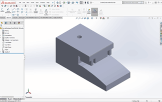
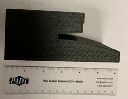
If you’ve been thinking of trying out Nylon 12 Carbon Fiber (12CF) to replace aluminum tooling or create strong end-use parts, do it! All the parts we’ve built here at PADT have shown themselves to be extremely strong and durable and we think you should consider evaluating this material.
Nylon 12CF filament consists of black Nylon 12 filled with chopped carbon fibers; it currently runs on the Stratasys Fortus 380cf, Fortus 450 and Fortus 900 FDM systems when set up with the corresponding head/tip configuration. (The chopped fiber behavior requires a hardened extruder and the chamber runs at a higher temperature.) We’ve run it on our Fortus 450 and found with a little preparation you get excellent first-part-right results.


With Nylon 12CF, fiber alignment is in the direction of extrusion, producing ultimate tensile strength of 10,960 psi (XZ orientation) and 4,990 psi (ZX orientation), with tensile modulus of 1,100 ksi (XZ) and 330 ksi (ZX). By optimizing your pre-processing and build approach, you can create parts that take advantage of these anisotropic properties and display behavior similar to that of composite laminates.
Best Practices for Successful Part Production
Follow these steps to produce best-practice Nylon 12CF parts:
- Part set-up in Insight or GrabCAD Print software:
-
- If the part has curves that need a smooth surface, such as for use as a bending tool, orient it so the surface in question builds vertically. Also, set up the orientation to avoid excess stresses in the z-direction.
-
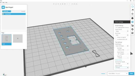
- The Normal default build-mode selection works for most parts unless there are walls thinner than 0.2 inches/0.508 mm; for these, choose Thin Wall Mode, which reduces the build-chamber temperature, avoiding any localized overheating/melting issues. Keep the default raster and contour widths at 0.2 inches/0.508 mm.
-
- For thin, flat parts (fewer than 10 layers), zoom in and count the number of layers in the toolpath. If there is an even number of layers, create a Custom Group that lets you define the raster orientation of the middle two layers to be the same – then let the rest of the layers alternate by 90 degrees as usual. This helps prevent curl in thin parts.
-
- Set Seam Control to Align or Align to nearest, and avoid setting seams on edges of thin parts; this yields better surface quality.
2. In the Support Parameters box, the default is “Use Model Material where Possible” – keep it. Building both the part and most of the surrounding supports from the same material reduces the impact of mismatched thermal coefficient of expansion between the model and support materials. It also shortens the time that the model extruder is inactive, avoiding the chance for depositing unwanted, excess model material. Be sure that “Insert Perforation Layers” is checked and set that number to 2, unless you are using Box-style supports – then select 3. This improves support removal in nearly enclosed cavities.
3. Set up part placement in Control Center or GrabCAD Print software: you want to ensure good airflow in the build chamber. Place single parts near the center of the build-plate; for a mixed-size part group, place the tallest part in the center with the shorter ones concentrically around it.
4. Be sure to include a Sacrificial Tower. This is always the first part built, layer by layer, and should be located in the right-front corner. Keep the setting of Full Height so that it continues building to the height of the tallest part. You’ll see the Tower looks very stringy! That means it is doing its job – it takes the brunt of stray strings and material that may not be at perfect temperature at the beginning of each layer’s placement.

5. Run a tip-offset calibration, or two, or three, on your printer. This is really important, particularly for the support material, to ensure the deposited “bead” is flat, not rounded or asymmetric. Proper bead-profile ensures good adhesion between model and support layers.
6. After printing, allow the part to cool down in the build chamber. When the part(s) and sheet are left in the printer for at least 30 minutes, everything cools down slowly together, minimizing the possibility of curling. We have found that for large, flat parts, putting a 0.75-inch thick aluminum plate on top of the part while it is still in the chamber, and then keeping the part and plate “sandwiched” together after taking it out of the chamber to completely cool really keeps things flat.
7. If you have trouble getting the part off the build sheet: Removing the part while it is still slightly warm makes it easier to get off; if your part built overnight and then cooled before you got to it, you can put it in a low temp oven (about 170F) for ten (10) to 20 minutes – it will be easier to separate. Also, if the part appears to have warped that will go away after the soluble supports have been removed.
Be sure to keep Nylon 12CF canisters in a sealed bag when not in use as the material, like any nylon, will absorb atmospheric moisture over time.
Many of these tips are further detailed in a “Best Practices for FDM Nylon 12CF” document from Stratasys; ask PADT for a copy of it, as well as for a sample or benchmark part. Nylon 12 CF offers a fast approach to producing durable, custom components. Discover what Nylon 12CF can mean for your product development and production groups.
PADT Inc. is a globally recognized provider of Numerical Simulation, Product Development and 3D Printing products and services. For more information on Nylon 12CF and Stratasys products, contact us at info@padtinc.com.


