
ANYSY HFSS provides many options for creating non-planar and conformal shapes. In MCAD you may use shapes such as cylinders or spheres, and with some steps, you can design you antennas on various surfaces. In some applications, it is necessary to study the effect of curvatures and shapes on the antenna performance. For example for wearable antennas it is important to study the effect of bending, crumpling and air-gap between antenna and human body.
Equation Based Surface
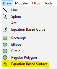
One of the tools that HFSS offers and can be used to do parametric sweep or optimization, is “Draw equation based surface”. This can be accessed under “Draw” “Equation Based Surface” or by using “Draw” tab and choosing it from the banner (Fig. 1)


Once this is selected the Equation Based Surface window that opens gives you options to enter the equation with the two variables (_u, _v_) to define a surface. Each point of the surface can be a function of (_u,_v). The range of (_u, _v) will also be determined in this window. The types of functions that are available can be seen in “Edit Equation” window, by clicking on “…” next to X, Y or Z (Fig. 2). Alternatively, the equation can be typed inside this window. Project or Design Variables can also be used or introduced here.


For example an elliptical cylinder along y axis can be represented by:

This equation can be entered as shown in Fig. 3.

Variation of this equation can be obtained by changing variables R1, R2, L and beta. Two examples are shown in Fig. 4.

Application of Equation Based Surface in Conformal and Non-Planar Antennas
To make use of this function to transfer a planar design to a non-planar design of interest, the following steps can be taken:
- Start with a planar design. Keep in mind that changing the surface shape can change the characteristics of the antenna. It is a good idea to use a parameterized model, to be able to change and optimize the dimensions after transferring the design on a non-planar surface. As an example we started with a planar meandered line antenna that works around 700MHz, as shown in Fig. 5. The model is excited by a wave port. Since the cylindrical surface will be built around y-axis, the model is transferred to a height to allow the substrate surface to be made (Fig 5. b)

- Next, using equation based surface, create the desired shape and with the same length as the planar substrate. Make sure that the original deisgn is at a higher location. Select the non-planar surface. Use Modeler->Surface->Thicken Sheet … and thicken the surface with the substrate thickenss. Alternatively, by choosing “Draw” tab, one can expand the Sheet dropdown menu and choose Thicken Sheet. Now select the sheet, change the material to the substrate material.

- At this point you are ready to transfer the antenna design to the curved surface. Select both traces of the antenna and the curved substrate (as shown in Fig. 7). Then use Modeler->Surface->Project Sheet…, this will transfer the traces to the curved surface. Please note that the original substrate is still remaining. You need not delete it.


Fig. 7. Steps for transferring the design to the curved surface (b)

Fig. 7. Steps for transferring the design to the curved surface (c)
- Next step is to generate the ground plane and move the wave port. In our example design we have a partial ground plane. For ground plane surface we use the same method to generate an equation based surface. Please keep in mind that the Z coordinate of this surface should be the same as substrate minus the thickness of the substrate. (If you thickened the substrate surface to both sides, this should be the height of substrate minus half of the substrate thickness). Once this sheet is generate assign a Perfect E or Finite Conductivity Boundary (by selecting the surface, right click and Assign Boundary). Delete the old planar ground plane.

Wave Port Placement using Equation Based Curve
A new wave port can be defined by the following steps:
- Delete the old port.
- Use Draw->Equation Based Curve. Mimicking the equation used for ground plane (Fig. 9).

- Select the line from the Model tree, select Draw->Sweep->Along Vector. Draw a vector in the direction of port height. Then by selecting the SweepAlongVector from Model tree and double clicking, the window allows you to set the correct size of port height and vector start point (Fig. 10).
- Assign wave port to this new surface.

Similar method can be used to generate (sin)^n or (cos)^n surfaces. Some examples are shown in Fig. 11. Fig. 11 (a) shows how the surface was defined.

Effect of Curvature on Antenna Matching
Bending a substrate can change the transmission line and antenna impedance. By using equation based port the change in transmission line impedance effect is removed. However, the overall radiation surface is also changed that will have effects on S11. The results of S11 for the planar design, cylindrical design (Fig. 8), cos (Fig. 11 b), and cos^3 (Fig. 11 c) designs are shown in Fig. 12. If it is of interest to include the change in the transmission line impedance, the port should be kept in a rectangular shape.

Equation based curves and surfaces can take a bit of time to get used to but with a little practice these methods can really open the door to some sophisticated geometry. It is also interesting to see how much the geometry can impact a simple antenna design, especially with today’s growing popularity in flex circuitry. Be sure to check out this related webinar that touches on the impact of packaging antennas as well. If you would like more information on how these tools may be able to help you and your design, please let us know at info@padtinc.com.
You can also click here to download a copy of this example.


