In a previous life, I worked in the maritime and offshore energy industries and used ANSYS as part of my daily routine in structural design. I eventually discovered myself in a position where I was designing subsea equipment for use in offshore oil and gas fields. One thing I quickly discovered was that although subsea structures tend to be fairly simplistic looking (think playground equipment…but 10000 feet underwater) there are multiple design factors that can easily cause a domino effect that would require redesign(s). Whether it was a change brought upon by the client, tool manufacturer, or to satisfy the whims of marine warranty companies, there was always a need to evaluate multiple variants of any subsea structure.
Sounds like a very reactive process, right? So how can we bring this process into a more streamlined analysis workflow within ANSYS? Just use parameters with SpaceClaim and ANSYS Mechanical!
So what can parameters do to aid in this process?
- Remove repetitive tasks
- Account for geometric changes to CAD models
- Use a range of values for material properties
- Create associative connections between CAD models and ANSYS results
- Allow for automatic goal driven design exploration
Now let’s look at some common use cases for parameters that I’ve run into in the past:
Accelerations for Onboard Equipment and Cargo
Cargo transported on the ocean is subject to the same accelerations that affect the vessel transporting it (surge, sway, heave, pitch, roll, and yaw). These accelerations are then combined into three representative accelerations and applied in multiple loadcases.
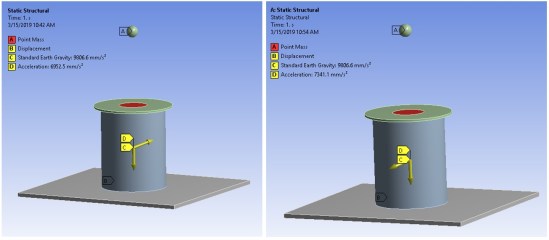
Typically, these loadcases are resolved in independent analysis systems but we can remove all that fluff with a simple parameter driven analysis. All one has to do is tag inputs and result items as parameters and then input values for each load case (or Design Point). In this case I have selected the XYZ components of an acceleration input applied to a mass point as well as the total deformation and maximum equivalent stress. With the push of a button ANSYS will then solve all of these design points and will amend the table to show the selected results corresponding with each design point. Results from the Design Points can be uploaded individually but this parametric analysis has made it very easy for us to determine which Design Points / load cases have the greatest influence on the design.

Geometry Influence Study
So one of the questions often asked during the design process is “Will the design work after we change this dimension to compensate for X?” which is often followed by a discussion on robustness (which is then followed by a change order). So let’s skip the discussion middle-man and move to be proactive by using parameters to quantify just how much we can change our geometry before a problem arises.
Here we have an example subsea Pipeline End Termination (PLET) structure and let’s say a client has asked us to verify if this design can work for various pipeline sizes. The PLET has some major parts that can be influenced by this change: The pipeline clamp, cradle, flanges, ball valve, and bulkhead.
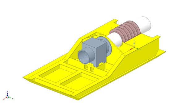
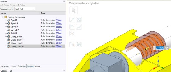
Because we can use parameters there’s no need to make a new model. Merely tag items you wish to create parameters for in SpaceClaim:
Then ANSYS Workbench will start to populate its parameter tables accordingly:
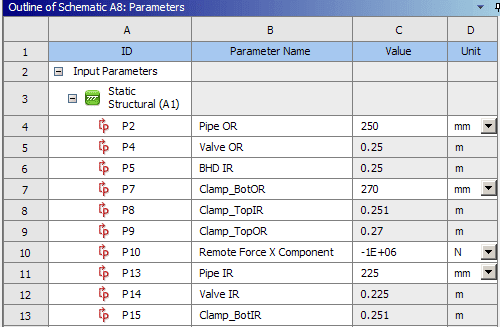
We can then make certain parameters dependent on others, or define them via simple expressions. In this way we can enforce clearances and relations between the various bodies in our model.

From here all we have to do is define our variables for our future analyses:
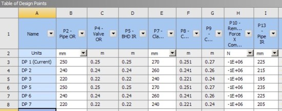
Then tell ANSYS to solve all the design points with a single click. Note that users can create charts and tables before the solve and ANSYS will populate these live during the solution process. Individual design point results and geometries can also be reviewed at any time.

For this particular analysis we provided the same load to each Design Point but a good next step would be to set a goal driven analysis and have a range of loadings on the pipeline end of the PLET to represent various installation conditions.
Parameters are a very powerful tool within the ANSYS toolbox. They can remove repetitive tasks within FEA, easily create loadcases, and address concerns about design robustness by letting ANSYS and SpaceClaim handle CAD model rework.
That’s it for this blog post! I’ll be creating a few offshore industry-specific posts in the future as well so stay tuned!


