Ansys Polyflow is a Finite Element CFD solver with unique capabilities that enable simulation of complex non-Newtonian flows seen in the polymer processing industry. In recent releases, Polyflow has included templates to streamline two of its most common use cases: blow molding and extrusion. Similarly, Ansys Discovery AIM offers a modern user interface that guides users through blow molding and extrusion workflows while still using the proven Polyflow solver under the hood. It is not uncommon for engineers to be unsure about which tool to pursue for their specific application. In this article, I will focus on the blow molding workflow. More specifically, I will point out three features in Polyflow that have not yet been incorporated into Discovery AIM:
- The PolyMat curve fitting tool to derive viscoelasticity model input parameters from test data
- Automatic parison thickness mapping onto an Ansys Mechanical shell mesh
- Parison Programming to optimize parison thickness subject to final part thickness constraints
Keep in mind that either tool will get the job done in most applications, so let us first quickly review some of the core features of blow molding simulations that are common to Polyflow and AIM:
- Parison/Mold contact detection
- 3-D Shell Lagrangian automatic remeshing
- Generalized Newtonian viscosity models
- Temperature dependent and multi-mode integral viscoelastic models
- Time dependent mold pressure boundary conditions
- Isothermal or non-isothermal conditions
For demonstration purposes, I modeled a sweet submarine toy in SpaceClaim. Unfortunately, I think it will float, but let’s move past that for now.
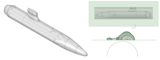
Figure 1: Final Submarine shape (Left), Top View of Mold+ Parison (Top Left), Side View of Mold+Parison (Bottom Right)
At this point, you could proceed with Discovery AIM or with Polyflow without any re-work. I’lll proceed with the Polyflow Blow Molding workflow to point out the features currently only available in Polyflow.
PolyMat Curve Fitting Tool
With the blow molding template, you can select whether to treat the parison as isothermal or non-isothermal and whether to model it as general Newtonian or viscoelastic. Suppose we would like to model viscoelasticity with the KBKZ integral viscoelastic model because we were interested in capturing strain hardening as the parison is stretched. The inputs to the KBKZ model are viscosity and relaxation times for each mode. If they are known, the user can input the values directly. This is possible in Discovery AIM as well. However, the PolyMat tool is unique to Polyflow. PolyMat is a built-in curve fitting tool that helps generate input parameters for the various viscosity model available in Polyflow using material data. This is particularly useful when you do not explicitly have the inputs for a viscoelastic model, but perhaps you have other test data such as oscillatory and capillary rheometry data. In this case I have with the loss modulus, storage modulus and shear viscosity for a generic high density polyethylene (HDPE) material. For this material, four modes are enough to anchor the KBKZ model to the data as shown below. We can then load the viscosity/relaxation time into Polyflow and continue.
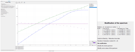
Figure 2: Curve Fitting of G’(Ω),G’’(Ω),η() [Left], KBKZ Viscoelastic Model inputs (Right)
The main output of the simulation is the final parison thickness distribution. For this sweet submarine, the initial parison thickness is set to 3mm and the final thickness distribution is shown in the contour plot below.
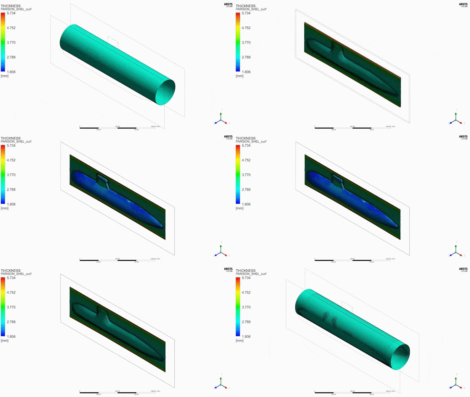
Figure 3a: Animation of blow molding process
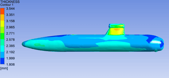
Figure 3b: Final Part Thickness Distribution
Thickness Mapping to Ansys Mechanical
The second Polyflow capability I’d like to point out is the ability to easily map the thickness distribution onto an Ansys mechanical shell mesh. You can map the thickness onto an Ansys Mechanical shell mesh by connecting the polyflow solution component to a structural model in workbench as shown below. The analogous work flow in AIM, would be to create a second simulation for the structural analysis, but you would be confined to specifying a constant thickness.
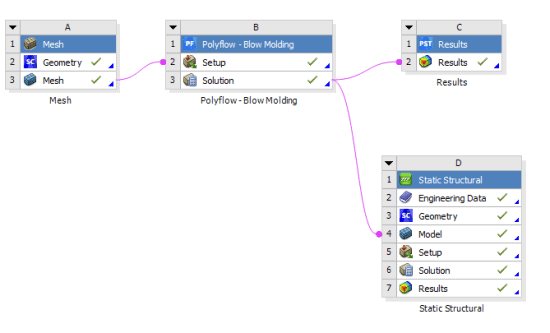
Figure 4: Polyflow – Ansys Mechanical Parison Thickness Mapping
In Ansys Mechanical, the mapping comes through within the geometry tree as shown below. The imported Data Transfer Summary is a good way to ensure the mapping behaves as expected. In this case we can see that 100% of the nodes were mapped and the thickness contours qualitatively match the Polyflow results in CFD -Post.

Figure 5: Imported Thickness in Ansys Mechanical
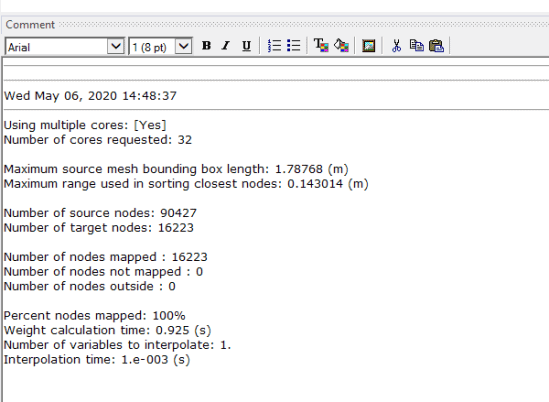
Figure 6: Thickness Data Transfer Summary
A force is applied normal to front face of the sail and simulated in Mechanical. The peak stress and deformation are shown below. The predicted stresses are likely acceptable for a toy, especially since my toy is a sweet submarine. Nonetheless, suppose that I was interested in reducing the deformation in the sail under this load condition by thickening the extruded parison. A logical approach would be to increase the initial parison thickness from 3mm to 4mm for example. Polyflow’s parison programming feature takes the guesswork out of the process.
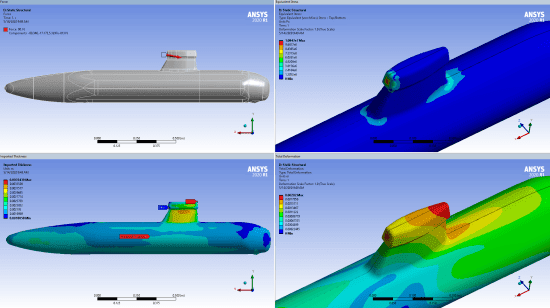
Figure 7: Clockwise from Top Left: Applied Load on Sail, Stress Distribution, total Deformation, Thickness Distribution
Parison Programming
Parison programming is an iterative optimization work flow within Polyflow for determining the extruded thickness distribution required to meet the final part thickness constraints. To activate it, you create a new post processor sub-task of type parison programming.

Figure 8: Parison Programming Setup
The inputs to the optimization are straight forward. The only inputs that you typically would need to modify are the direction of optimization, width of stripes, and list of (X,h) pairs. The direction of optimization is the direction of extrusion which is X in this case. If the extruder can vary parison thickness along “stripes” of the parison, then Polyflow can optimize each stripe thickness. The list of (X,h) pairs serves as a list of constraints for the final part thickness where X is the location on the parison along the direction of extrusion and h is the final part thickness constraint.
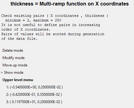
Figure 9: Thickness Constraints for Parison Programming
In our scenario, the X,h pairs form a piecewise linear thickness distribution to constrain the area around the sail to have a 3.5mm thickness and 2mm everywhere else. After the simulation, Polyflow will write a csv file with to the output directory containing the initial thickness for each node for the next iteration. You will need to copy over the csv file from the output directory of iteration N to the input directory of iteration N+1. The good news is the optimization converges within 3-5 iterations.
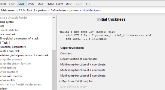
Figure 10: Defining the Initial Thickness for the Next Parison Programming Iteration
Polyflow will print the parison strip thickness distribution for the next iteration in the .lst file. The plot below shows the thickness distribution from the first 3 iterations. Note from the charts below that the distribution converged by iteration 2; thus iteration 3 was not actually simulated. The optimized parison thickness distribution is also plotted in the contour plot below.
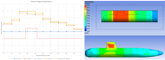
Figure 11: Optimized Parison Thickness (Top), Final Part Thickness (Bottom)
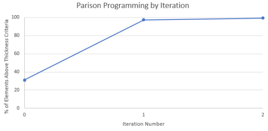
Figure 12: % of Elements At or Above Thickness Criteria
As a final check, we can evaluate how the modification to the parison thickness reduced the deformation of the submarine. The total deformation contour plot below confirms that the peak deformation decreased from 2mm to 0.8mm.

Figure 13: Total Deformation in Ansys Mechanical After Parison Programming
Summary
Ansys Discovery AIM is a versatile platform with an intuitive and modern user interface. While Aim has incorporated most of the blow molding simulation capabilities from Polyflow, some advanced functionality has not yet been brought into AIM. This article simulated the blow molding process of a toy submarine to demonstrate three capabilities currently only available in Polyflow: the PolyMat curve fitting tool, automatic parison thickness mapping to Ansys Mechanical, and parison programming. Engineers should consider whether any of these capabilities are needed in their application next time they are faced with the decision to create a blow mold simulation using Ansys Discovery AIM or Polyflow.


