
Friday Flownex Tech Tips #12
As a System Engineer you may not always already have equipment decided on for your particular network. Flownex makes it easy to start from scratch and will help determine the equipment necessary to meet the flow or process requirements. In today’s tip we’ll go over how to size a pump using the basic centrifugal pump component and how to manually enter pump curve data. We are using Flownex version 8.12.7.4334
Sizing a Pump
In our example scenario let us pretend we are sizing a pump for a cooling water circuit. We are tasked with finding a pump which will deliver water at a rate of 1 kg/s to the heat exchanger. We know our upstream and downstream boundary conditions as well as the heat added at the exchanger and the speed at which we will be operating the pump.
Choose the appropriate flow component
There are a few different pumps available in Flownex:

Basic Centrifugal Pump: Used when we do not have a pump chart available, particularly useful when sizing a pump.

Fan or Pump: Used when a pump chart is available for modeling either compressible or incompressible flows.

Positive Displacement Pump: Used for modeling rotary and reciprocating pumps where the fluid is incompressible, non-Newtonian, or a slurry.

Variable Speed Pump: Similar to the Fan or Pump but with the ability to interpolate between fan/pump curves for different speeds of rotation.
In this case we’d choose the Basic Centrifugal Pump. This is found in the component pane under Turbos and Pumps. Since we only know the RPM we can enter it in the inputs under Speed at BEP:

Recall we don’t know what the design of the pump will be. Since all we know is that the mass flow rate needs to be 1 kg/s we will check the box for fixed mass flow and then select to change design to target our desired flowrate.

Once we hit solve our pump design inputs will be populated such that our desired mass flow rate is achieved. We can cross-reference these values with available pumps to choose the appropriate component for our network!

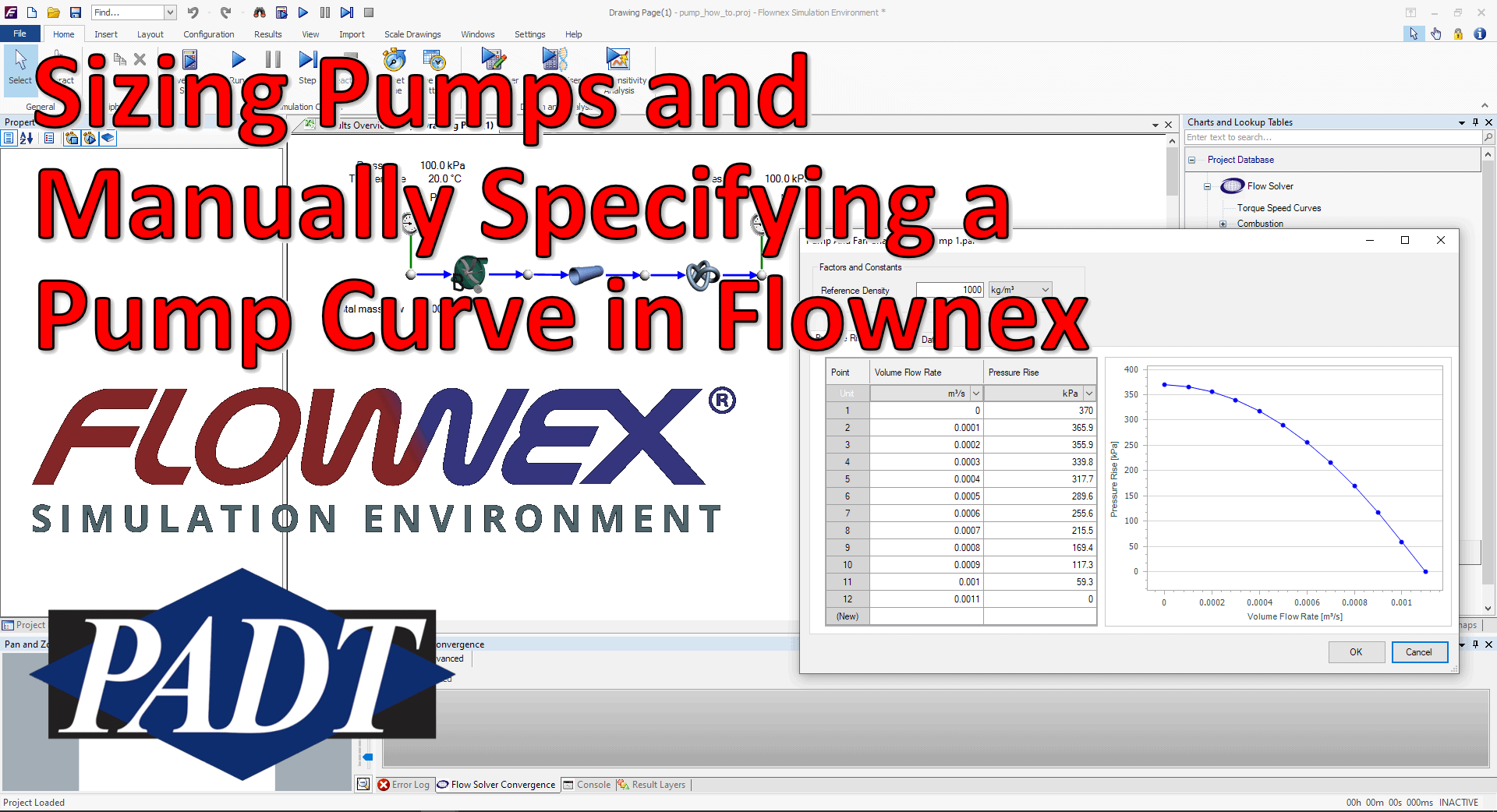
Specifying a Pump Curve
If we already know which pump we are using, or perhaps are trying to decide between several available pumps, we may need to add these pump curves to Flownex. To add a pump curve we will navigate to the Charts and Lookup Tables pane > Project Database > Flow Solver > Turbos and Pumps. In this scenario we are looking at a single speed pump so we will right-click on Pump and Fan Charts and Add a Category.

We can name our category whatever is appropriate and then right-click on the newly created category to add our own pump chart.

To edit the newly created pump chart we can either double-click on it or right-click and select edit. Now we simply specify the Reference Density and then fill out the table with the relevant data points. To speed things along we can copy and paste a table of data points from excel or whatever source we get this curve from. Don’t forget to check your units!

Bonus Tip!
- Don’t forget you can save created pump charts in a shared database (see previous blog post on creating a shared database)


