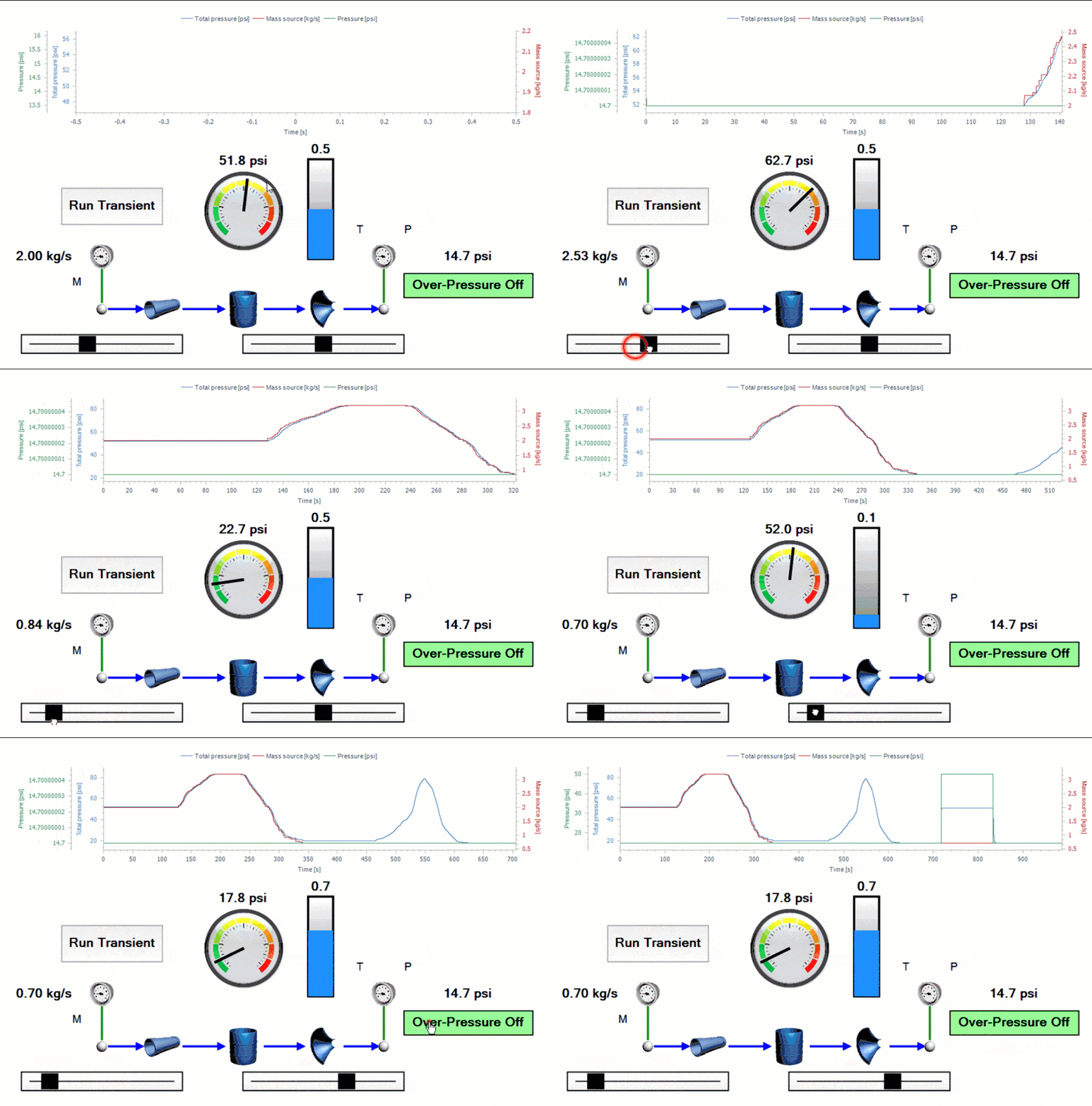
Flownex Tech Tips!
No, robots are not taking over… yet… Luckily, Flownex has human machine interface controls available so that we can interact with our system simulation. Let’s go over how to maintain human control of our system using an HMI. For this demo I am using Flownex version 8.12.8
Visualization Library
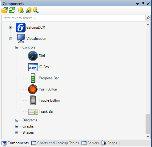
In the Components pane near the bottom we can find our human machine interface (HMI) components in the Controls category. We have a few components here which we’ll go over use cases for. As a reminder, if we want to learn more about a specific component we can always select the component and press F1 on our keyboard to bring up the library manual for that specific component.
Dial
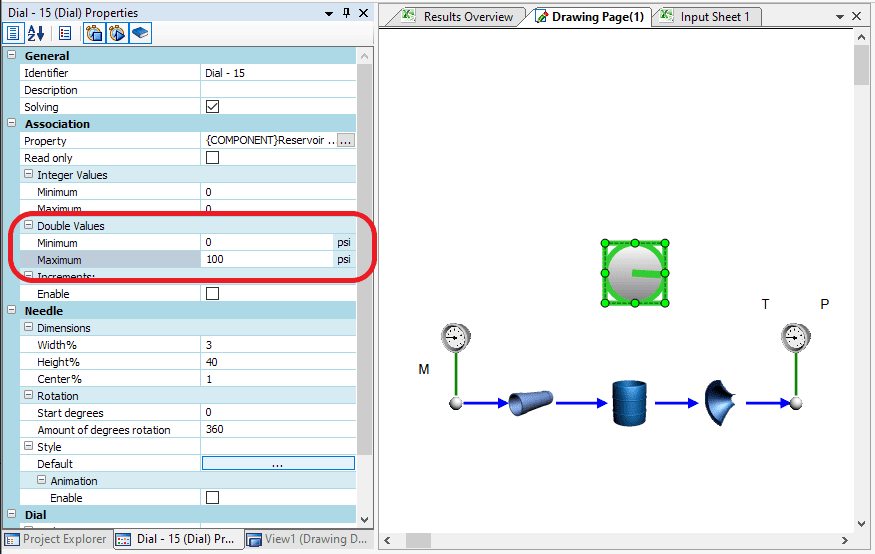
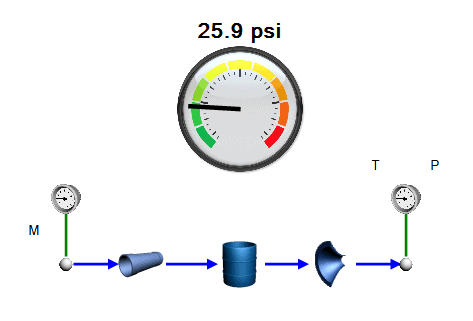
No, the phone call is not coming from inside the house! We can use the dial component to visualize any property, usually a result, in a dial interface. To use the dial component we simply drop it into our network and then drag and drop the property we’re interested in onto the component itself.
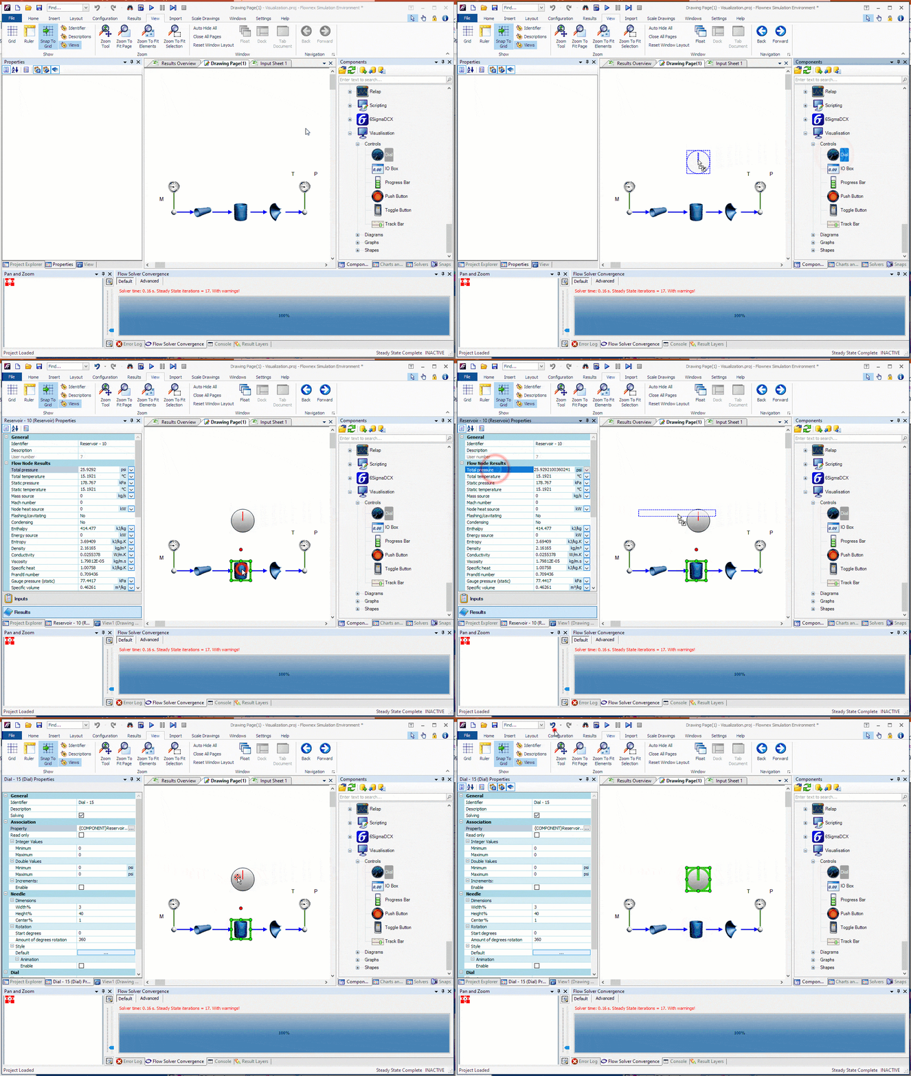
We must set the minimum and maximum values for our dial, in this case since we are reporting the pressure we will want the variable type to be Double. If we want to get fancy we can change our start degrees, amount of rotation, even replace the gradient background with an image from an actual dial!
IO Box
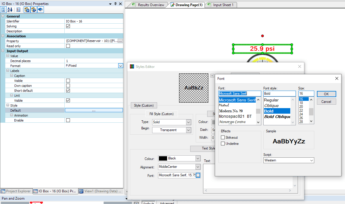
The IO Box is probably something we’ve already been using without even realizing it. This is what is created whenever we drag an input or result property onto the canvas. In the image with the dial we use an IO box to report the pressure in our reservoir. We can attach properties to IO boxes by dragging and dropping. In the properties of the IO box we can change the font, size, units, how many significant figures are reported, and more.
Progress Bar
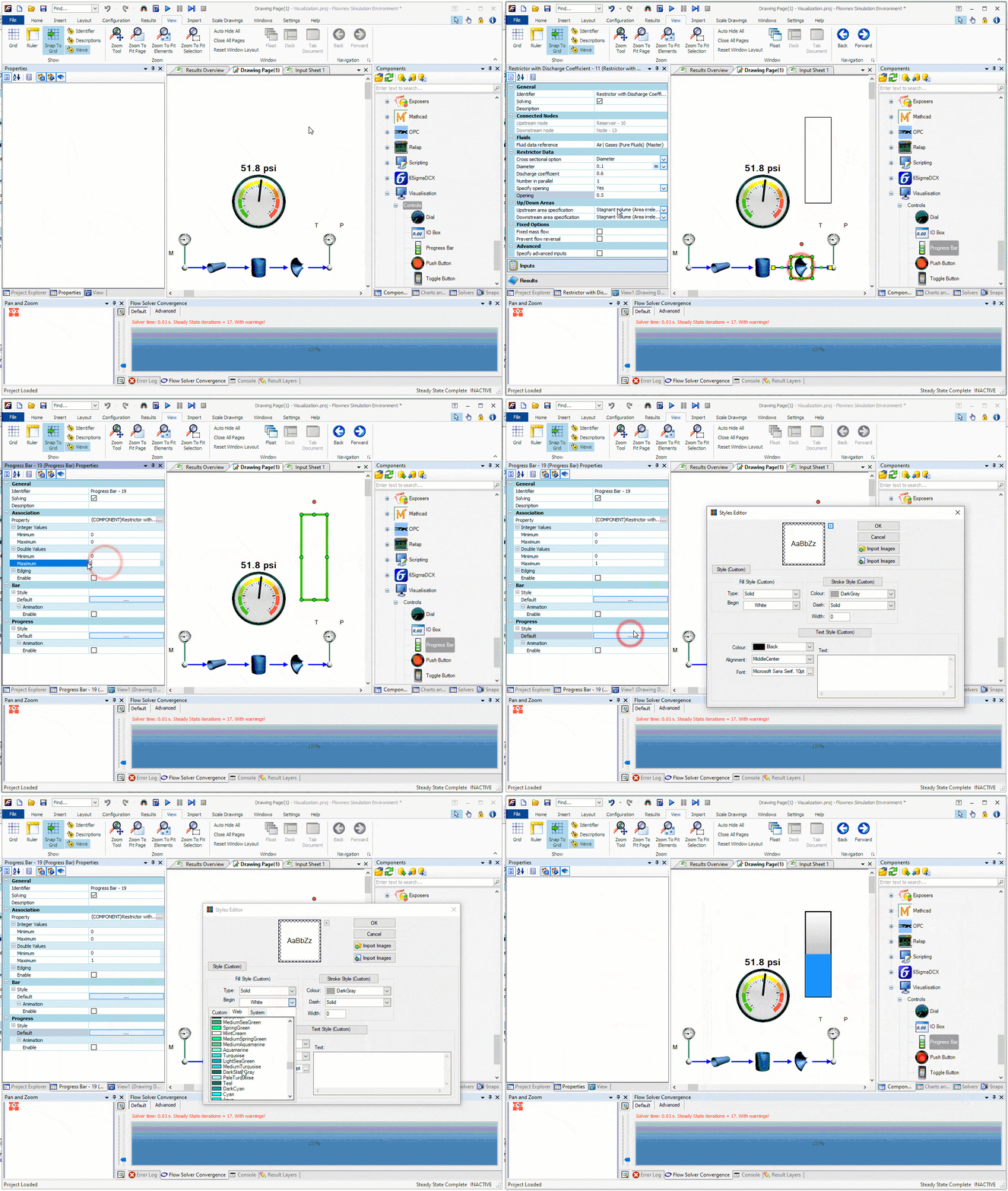
The Progress Bar is used in very similar situations as the dial however I find it to be particulary useful when reporting fill levels in containers or reporting valve fractions open. We’ll tie the “fraction open” of the restrictor component downstream of the reservoir to our progress bar.
Push Button
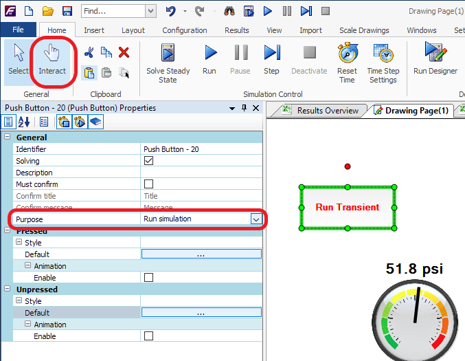
The Push Button can be used for a variety of operations (selectable via drop-down in the inputs). I most often use these to run scripts, start, or stop a transient simulation. We have all of the similar formatting options as we’ve seen with these other tools. It is important to note that in order to interact with the push button we need to be in “Interact Mode” found on the home ribbon.
Toggle Button
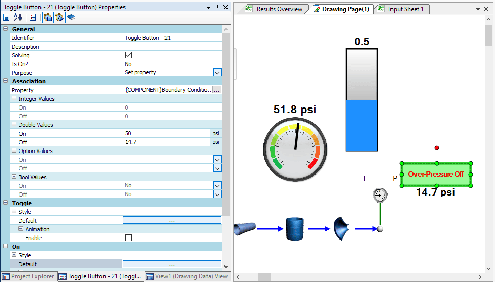
The Toggle Button is going to be similar to the push button but has distinctive on vs off characteristics. We most often would use this to set a property. This can, again, be set up by dragging and dropping the property onto the button. What I’ll do in this example is have the toggle button set up to toggle our downstream pressure boundary condition between 14.7 psi and 50 psi to simulate an overpressure event. We can go into the different style menus to make our button more aesthetically pleasing and change the text, etc.
Track Bar
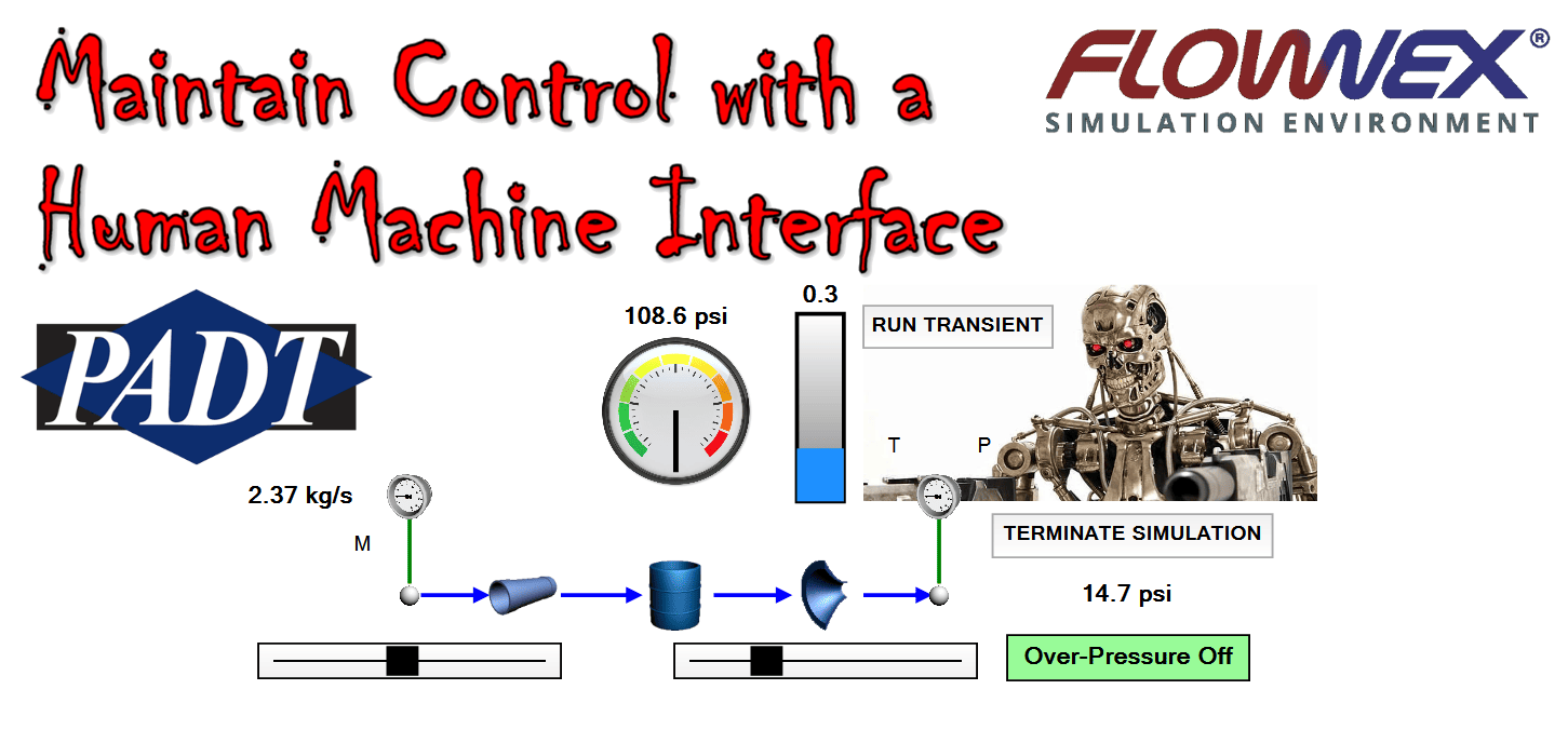
The Track Bar is a slider which allows us to vary an input via interaction. We’ll use two track bars in this example; One to control the mass flowrate at the inlet and a second to control the fraction open of the restrictor. To tie a property to a trackbar we again drag and drop the property and then update the track bar’s minimum and maximum values to give us the range of operation. The complete network with all of the HMI components can be seen below (remember we are in “Interact” mode):
