

If you’ve worked much with 3D printed polymer parts, specifically those produced with melted filament, you know that generally you can machine the final product. Adding a hole, enlarging or tapping a hole, finishing a surface or even cutting off a section are all possible steps in secondary processing.
The challenge is that most information about just how to do so tends to be anecdotal. PADT talked to several experts who work with filament printers such as Stratasys fused deposition modeling (FDM) systems to gather tips and tricks for successful machining across a variety of FDM polymer materials.
First, some basics. The machining functions we’ll talk about here are drilling, milling, turning and sawing. These processes have been done for thousands of years on wood, stone, metal and other materials, as well as on standard (solid stock) plastics so there’s a wealth of experience with general tool design and application.
Anyone working with these processes soon becomes familiar with “feeds and speeds” as the primary settings. (If these terms are already second-nature to you, skip ahead to the Advice section.)

Feed Rate (F) is an important factor in determining total machining time and the roughness of the finished part (when you’re talking about working the overall surface or removing material from a part face). Feed rate is defined as the linear distance the cutting tool travels during one spindle revolution, as the cutter moves along the part’s contour. If you are turning or boring a part, it can be listed as either inches per revolution (ipr) or millimeters per revolution (mpr); when tapping a hole, the number of threads will influence this value. For milling, it’s more common to use inches per minute (ipm) or millimeters per minute (mpm).
Cutting (or Spindle) Speed is the relative velocity between the cutting tool and the part’s contact surface. You can also think of it as the speed with which the part is moving past the tool’s cutting edge, given in either revolutions per minute (RPM), meters per minute (m/min) or feet per minute (ft/min). Since this is also an important factor in how the cutting teeth or flutes create chips of removed material, tool catalogs give specs as mm/tooth/revolution. Cutting speed influences how much the part and tool heat up in use, as well as overall tool life. In general, the harder the part material, the slower the cutting speed that should be used. (Note: You may find that using a single-flute end-mill helps avoid chip build-up but be aware that since such a tool has a highly exposed edge, they are very sharp – be careful when handling.)
Some good information on flute configuration versus feeds-and-speeds is available at Why Flute Count Matters – In The Loupe – Machinist Blog (harveyperformance.com).
Advice for FDM Polymer Machining

FDM materials can be printed with many different approaches and therefore produce different results when machining. For example, is the part solid or was the interior formed with a type of lattice-structure creating alternating walls and holes? Was the part printed as near-net dimensionally as possible? Is there some type of composite structure involved?
At Stratasys headquarters in Eden Prairie MN, senior strategic application engineer Allen Kreemer says that polycarbonate (PC) and ULTEM are the most frequently machined FDM materials: “ULTEM 1010 cuts beautifully, PC can handle an aggressive feed-rate but requires a slower speed, and Nylon 12CF machines just fine.” He points out that ABS and ASA can be soft and gummy to drill but can work if you adjust your feeds and speeds, and says, “Engineers should ask their machinists to talk to their cutting-tool vendors for advice,” adding, “be sure to use air-cooling only – not cutting fluids.”
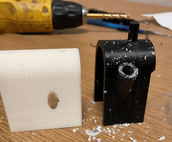
Kreemer explains that GrabCAD Print, one of the Stratasys software options for setting up parts, offers a very relevant capability: “Leverage the advanced features available when importing CAD data into GrabCAD Print by selecting any horizontal holes in your part and checking the box ‘make self-supporting.’” The software converts them to undersized, diamond-shaped holes, providing several benefits. Machine operators save time and material when printing the part due to no support material being applied to the holes. And, he adds, “An interesting fact is any standard two-flute drill bit in a cordless drill will center up perfectly in a four-sided hole, making the final part just what the customer wanted.”
A final note of advice from Kreemer is to monitor the part temperature to ensure the part is not expanding locally due to the relatively high CTE of most thermoplastics, as this will affect final part accuracy.
Thoughts from the Field
Lucas Stahl, an Additive Manufacturing process and hardware expert at a Fortune 500 industrial manufacturer, offers the following thoughts based on his years of experience in this field.
“There are not very many good, universal answers when it comes to polymer FDM parts,” says Stahl. “You will likely have different answers for different materials, parameters, and manufacturers of printers. The most important thing will be to ensure that any surface you are cutting has high density, well-adhered material surrounding it (more contours, more layers, etc.)”

He offers the following observations
- The biggest issue with FDM parts is that they will never be fully dense, and they will never have uniform density. Parts will act “softer” in some regions than others. Using as uniformly dense infill as possible will help reduce this issue. A gyroid lattice is beginning to become a popular option for many machines. (Note: Stratasys’ high-end part set-up software, Insight, offers a gyroid infill with variable sizing parameters.)
- When setting up your print, whether in CAD or in, say, GrabCAD Print, increase the number of layers or contours at each cut surface. This provides more mass.
- It’s important to print “pilot” holes centered on where you want to drill a larger hole. This will help you maintain density and surface integrity around the cut. Orientation of holes will also be extremely important: A vertical hole will machine easily, but horizontal holes will be prone to separating while machining.
- Print parts as near-net-dimension as possible, to minimize the amount of material to be removed.
- Take shallow cuts. The deeper the cut, the higher the likelihood of shearing between layers.
Machining Tips and Resources
PADT director and founder, Rey Chu, recommends following the general, traditional machining guidelines in the classic Machinery’s Handbook as well as plastic material supplier’s recommendations. He notes, “Those data were generated from machining bulk-plastics, but the material properties and behaviors are similar to FDM materials. Due to the weakness of layer-to-layer bond strength and inter- and intra-layer air gaps/porosity of FDM produced components, I would recommend lighter depth-of-cut to reduce cutting force on the workpiece. Compressed air cooling should be adequate.”
Another manufacturing engineer at a large aerospace company made these observations and suggestions:
- Feed per tooth is typically faster than what is used for working with metals.
- A reduced number of flutes means larger chip size and better heat management. For comparison, for harder thermoset CFP materials, 8-flute and higher routers work well.
- Use a conventional cutting direction in most cases to help extract heat through chip removal. If you are having issues with layer adhesion, swap to use a climb-cut method instead. (With conventional milling, the cutter rotates against the direction of the feed. During climb milling, the cutter rotates with the feed.)
- Use high speed steel (HSS) tooling for most plastics. Consider finding a cutter with a friction reducing coating such as ZRN coating; this will reduce adhesion of plastics to the cutting edge for better chip evacuation and heat management.
- For any printed material that is abrasive, use carbide routers, diamond coating or similar coatings to increase cutter life. (HSS would work but will dull in half the cutting time.)
- The higher the glass transition temperature of the part-material, the more forgiving it will be when it comes to cutter geometry, feed rates, and spindle speeds. The downside is that it will likely need a carbide cutting tool.
Multiple AM engineers have referenced Curbell Plastics as having good guidelines, particularly to help in selecting a specific cutting tool. Their online pages make such points as:
- More heat is generated in drilling than in most other machining processes. The feed rate should be reduced when the drill gets close to exiting the material.
- Care is required when clamping parts to prevent deformation.
- HSS tooling works well for milling most thermoplastics.
- Thick-walled parts should be sawed with relatively thin blades to avoid excessive frictional heat generation; specially designed blades are available.
- Smooth, polished top surfaces help reduce material build-up when turning parts.
Milling:
Turning:
Drilling:
Sawing:
Parting Thoughts
There is an older (2012) Edition of Machinery’s Handbook on-line that may be of interest. This has classically been written for use with metals, not thermoplastics (though it includes glass/semiconductor information). However, it includes general feeds-and-speeds tables as well as very thorough descriptions and diagrams about relevant machining terms and components.
PADT Inc. is a globally recognized provider of Numerical Simulation, Product Development and 3D Printing/3D Scanning products and services. For more information on Stratasys and EOS printers and materials, or GOM scanners, contact us at info@padtinc.com.


