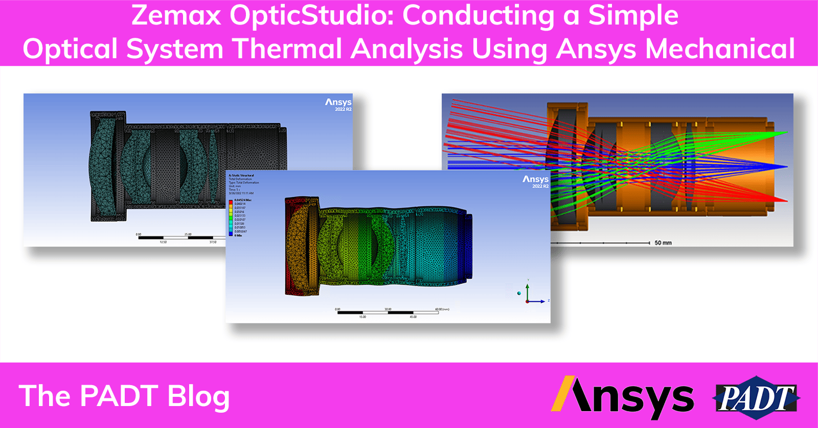
The Optics Engineer is back and ready to talk about the wonderful world of optical simulation. Today I will address how to perform a simple thermal analysis on an optical system to understand the temperature effects on optical performance.
Although Zemax OpticStudio does have thermal capabilities through the Environment tab of the System Explorer and the “Make Thermal” tool, this workflow will use Ansys Mechanical to analyze the system deformation of both the optics and mechanical tube assembly. Remember our Double Gauss example from the last blog post? It’s making a comeback to analyze system deformation due to different temperature soaks.
Getting Thermal Response Ansys Workbench for Zemax OpticStudio
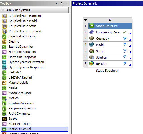
To begin, open a new project in Ansys Workbench. Drag and drop a Static Structural analysis into the Project Schematic.
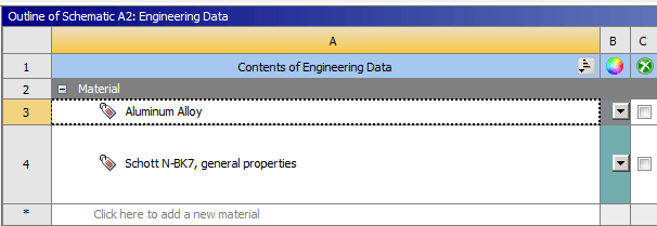
Right click on the Engineering Data cell to Launch the Engineering Data editor. From here, material properties for the system may be specified. For this example, an aluminum alloy was used for the mechanical parts and N-BK7 was used for the lenses. The aluminum alloy can be found within the Engineering Data Sources Library under the General Materials volume. N-BK7 can be found in Granta Selector. The JAHM Curve data for N-BK7 was exported from Granta Selector as an .xml file and imported into the Engineering Data Source Library.
Once the materials have been specified, the geometry can be imported into the project by right-clicking on the Geometry cell of the Static Structural analysis.

The geometry may be edited by right-clicking on the geometry cell and clicking “Edit Geometry in SpaceClaim…” For this example, the geometry provided is ready for analysis.
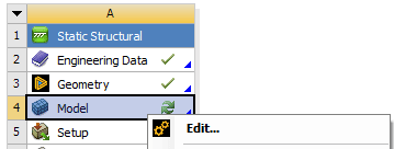
From here, the model must be edited from within Ansys Mechanical. Right-clicking on the Model cell and choosing “Edit” will open up Ansys Mechanical.
Once Ansys Mechanical is open, the material of each part needs to be defined. This can be done by clicking on each part under the Geometry branch and assigning material within the part’s Details window.
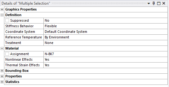
Clicking on the Coordinate Systems branch, you’ll notice that the Global Coordinate System was set to match the coordinate system of Zemax OpticStudio. This will make importing FEA data into Zemax OpticStudio with the Zemax STAR module run much smoother.
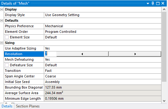
For this example, the default contacts will be sufficient for analysis. The contact types are all bonded, meaning that parts cannot separate, penetrate, or slide between each other. This example will also take advantage of the default mesh generated by Ansys Mechanical, with the exception of adjusting the resolution of the mesh to 7 from the default value of 2 for a finer mesh.
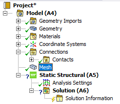
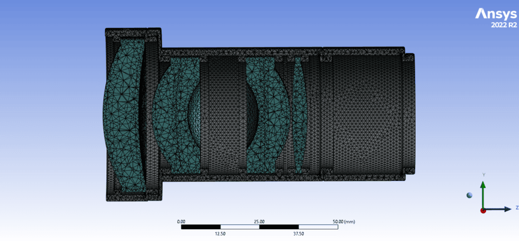
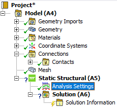
Once the system is meshed, the Analysis settings under the Static Structural branch can be updated for the thermal analysis. For this example, part deformation will be analyzed due to a change of environmental temperature from nominal. The temperature range is -10° to 40° C with 10° increments, therefore the simulation needs to run through 5 steps, each step lasting 1 second. This can be adjusted in the details window of “Analysis Settings” under the Static Structural branch.
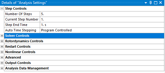
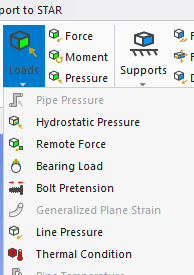
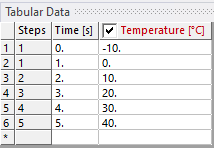
The thermal condition must now be defined. When clicking on the Static Structural branch in the project tree, the ribbon bar should have an Environment tab where the system loads can be chosen. From here a thermal condition can be defined by choosing “Thermal Condition” under “Loads.” The thermal condition should be applied to all 16 bodies and set up with 10° degree increments from -10 to 40° C.
We can also create a fixed support on the system to model the lens tube system being attached to a camera or detector. The fixed support is optional.
The last step before solving for the solution is to add solution results. This can be done by clicking on the Solution branch of the project tree. The Solution ribbon should appear. Under “Results” users can find different types of results to solve for. In this case Total Deformation and Directional Deformation will be used to analyze deformation due to different temperature soaks.
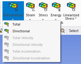
The solution can now be solved by right-clicking on the solution branch and clicking “Solve.”
The deformation results can be viewed by clicking on either the Total or Directional Deformation branch in the project tree. Results will be scaled to provide a clearer understanding of the system deformation. The initial results will include total system deformation under the 5 different temperature steps.
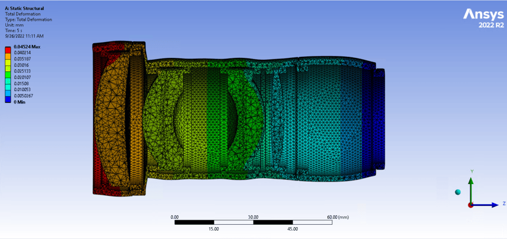
Users can step through the different temperature values and understand deformation at each temperature.
Thanks to the hard work from the Ansys and Zemax Teams, lens deformation results can be exported from Ansys Mechanical to be opened in Zemax OpticStudio using the STAR model for STOP analysis. To export the lens deformation data, the “Export to STAR” ACT extension must be downloaded from the Knowledgebase article: OpticStudio STAR Module: Ansys Data Export Extension – Knowledgebase (zemax.com).
The next steps would be to import the FEA data files into Zemax OpticStudio and do an analysis of the optical system performance at the different temperature soaks.
You can access our test model here:
If you would like to learn more about Zemax OpticStudio or other Ansys products, please reach out to the software support team at swsupport@padtinc.com. We would love to hear your feedback!

