
What’s the difference between Reverse Engineering and 3D Digitization? Reverse Engineering requires engineering problem solving to determine how a product/design met its required functionality and purpose. This can be done through several methods such as performance and material testing as well as 3D Digitization. 3D Digitization focuses solely on capturing the geometry of the design. It does not ask “why” the design was made that way. It simply does its best to copy exactly what a 3D scan captures. The results of 3D Digitization is a valuable tool that can help customers with their Reverse Engineering projects
Now that that’s out of the way, are you looking to get a part or multiple parts scanned for 3D Digitization? Do you know which file output matches your needs and capabilities? If not, fret not. Read on to decide which level is best for you.
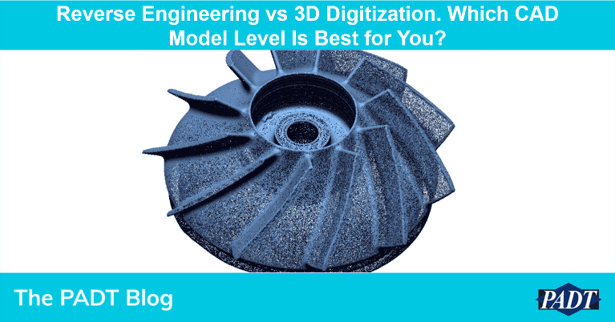
3D Digitization & CAD Models at PADT
PADT’s Manufacturing group uses an advanced suite of tools and technologies to digitize and create CAD models of physical parts. With access to structured light scanners, handheld laser scanners, and CT (Computed Tomography) scanners, we can determine the best technology to scan each part as needed.
The result from scanning is typically an STL file containing millions of points that may need to be modified or converted to a solid CAD model for future use. Geomagic Design X software is used to 3D digitize physical parts into digital parametric CAD models. Engineers within the Manufacturing group will use their years of experience, training, and our technologies and tools to build complete and comprehensive CAD models to the greatest degree of accuracy. Depending on our customer’s end use, budget, and requirements, we offer different levels of detail and solid model outputs.
Level 1: Point Cloud (.xyz, .asc, .pts)
A point cloud data type is composed of a group of vertices in three-dimension coordinates: X, Y, and Z.
Pros:
- Raw file format
- Ideal for visualization at higher resolution
- Less demand on computer GPU
- Low post-processing cost
Cons:
- No CAD editing capabilities for 3D digitization or reverse engineering
- Need specialty software to view

Level 2: MESH (.stl, .obj, .ply, .vrlm)
Mesh data, also known as a polygon file, contains numerous three-sided triangles with normal vectors to represent the outer surfaces of an object digitally. It consists of points, edges, and faces. Geomagic has tools that can be used to manipulate a mesh including optimizing the mesh for direct use in additive manufacturing, resolution control (decimate and subdivide meshes), mesh smoothing, repair, region editing, and much more.
Pros:
- Used for computer graphics rendering
- Ideal for CAD/CAM/CAE/RP
- Great for organic shapes
- Low post-processing cost
Cons:
- No CAD editing capabilities for 3D digitization or reverse engineering
- Planes, edges, and holes features are as captured and not perfect

Level 3: Surface Model or NURBS (STEP, IGES)
A mathematical CAD model that’s generated by fitting surface patches to an optimized mesh, creating an accurate surface body from a complex, freeform part. This method can be used to create model data for manufacturing or analyze geometric models of freeform shapes.
Pros:
- Ideal for freeform, organic models
- Used in CAD systems for design
- Accurate representation of part
- Modest post-processing cost
Cons:
- Limited direct editing in CAD
- Planes, edges holes, and features are as captured and not perfect
- Some post-processing required

Level 4: Parametric CAD (STEP, IGES, Parasolid)
A Parametric model is generated using a similar CAD systems approach that uses parameters but is derived from scanned data, defining design features and recreating a solid model.
Pros:
- Mechanical parts with prismatic features
- Captures design intent
- May include some freeform surface, hybrid modeling
Cons:
- Accurate representation of part as designed; may deviate slightly from scanned data
- High post-processing cost

Level 5: Parametric Feature-Based CAD (Solidworks)
LiveTransfer™ is used to recreate the native CAD model with parametric features and history tree included.
Pros:
- Fully editable in supported CAD systems
Cons:
- Inspection analysis may be necessary to show deviations from the scan data
- High post-processing cost

If interested in our 3D Digitization services or need additional assistance, please visit padtinc.com/3d-digitization or contact us at scan@padtinc.com
Follow us on Instagram for more 3D Printing & 3D Scanning content
Article written by PADT MFG Department


