
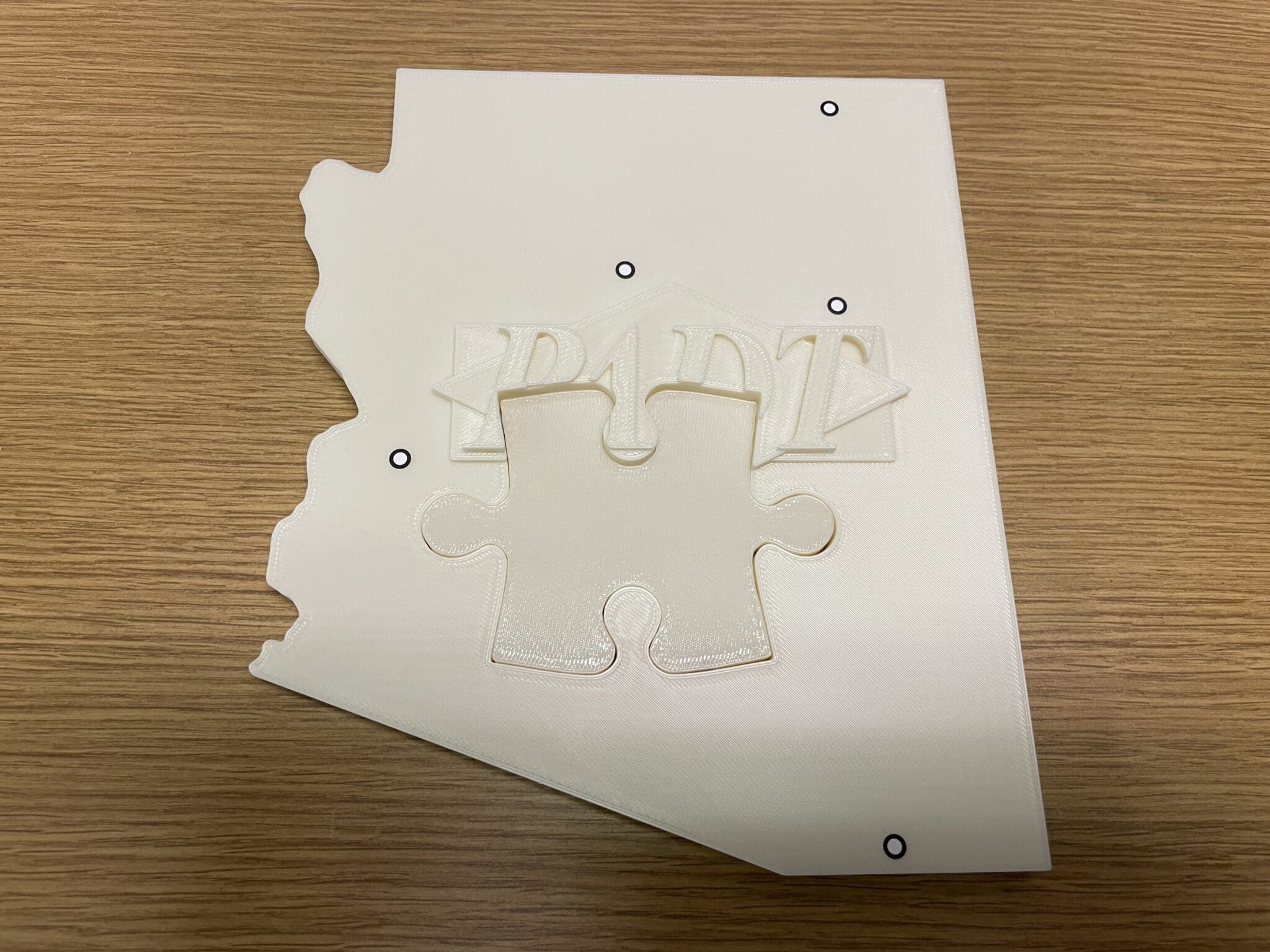

Oh, no – my favorite Arizona PADT puzzle is missing a piece!! What can I do to recreate the Phoenix/Tucson part? Luckily, I have access to reverse engineering tools with our ZEISS 3D scanning equipment. In less than five minutes, I took scan data with both the Tscan hawk handheld laser scanner and the ATOS Q blue-light triple-scan system. I knew I could use the outline of the missing piece in several ways, to generate a new 3D CAD model for 3D printing on our Stratasys FDM printer.
The Tscan hawk is a handheld system that can go anywhere and capture both overall and fine-detailed part features. With ZEISS GOM Inspect software for both data acquisition (point cloud) and data analysis (align to a coordinate system, clean up data, convert to a 3D mesh), I had a model in minutes.
Here’s a look at what the Tscan hawk saw of the top surface:

I also have the ZEISS ATOS Q blue-light system with interchangeable lens sets for best data-capture of varying fields of view. Using the 370mm set and the programmable turntable, I dug a little deeper, this time capturing the puzzle’s top and bottom and automatically transforming the data into a single part.
Here’s the ATOS Q version:

You can see this set-up achieves higher resolution, even showing the rastering from 3D printing. Both datasets would have worked, but I decided to use this latter file.
Converting scan data into CAD files for Reverse Engineering
There are many ways to work with scan data; the choice depends on your final goal, the software to which you have access and the level of accuracy you desire. GOM Inspect software converts the acquired point-cloud data into a mesh representing the surface, which I chose to export as a standard STL file.
To recreate my missing puzzle piece, I thought about how I could use that STL with one or more of the following packages in my workflow.
I didn’t need a parametric model, just a solid, printable CAD file. I ended up working with two approaches in ZRE, one of which flowed into Fusion 360, while my PADT colleague, Chase Wallace, brought the file into Solidworks and took a different path. (Even more approaches are possible.)
ZEISS Reverse Engineering: Two methods
Method 1 – fit cylindrical and planar faces to the curved surface > merge with planes > extrude
Method 2 – project the curve to a plane > copy > export to Fusion 360 > fit spline > extrude
For the surface-fitting method, you select the portion of the part that interests you:

Hide the rest of the part:

Then select and remove unwanted sections (top and bottom planes), to leave just the opening outlined:

Finally, create a Surface Approximation from Points, fitting (in this case) cylinders and flats as appropriate, based on a central axis, which gives you sections like this:

I could see where this would work Booleaned to a top and bottom surface, but I decided I also wanted to try working with spline curves. That meant using where it intersected with a plane as a projection, which would avoid any unevenness in the side-wall surface.
So, the second try went like this: create a mid-plane through the opening.

Viewing only the intersection yielded this (with some stray noise I hadn’t yet cleared, but I knew I could continue):

Lastly, I captured this as an image to bring into Autodesk Fusion 360 as a template and created a spline curve around it. Here’s what the final extruded (0.4 inches thick) model looks like:

When scaled to the dimensions of the actual part, and slightly undersized to fit with good clearance, it’s easily printable on our F370 FDM printer.
Solidworks Approach
Chase brought the GOM Inspect STL file directly into Solidworks and created a projection plane:

The next step was selecting points around the edge of the opening and connecting the points with a spline curve.

Performing an offset of this curve by 0.008 inches allowed good clearance to the other puzzle piece.
Lastly, by hiding the original part and doing a normal extrusion of 0.4 inches, the final part is ready to print. Here is the result:

Next steps would be to include the logo. I could see creating a separate solid body that would have the missing portions of the PADT logo, merging that body (Booleaned) with the extruded/created part, and recreating the missing piece exactly. I could also see oversizing the extrusion and 3D printing a mold as another approach to producing a new part. Having a digital model offers multiple possibilities, but for now, this works!
ZEISS scanners > ZEISS Reverse Engineering/CAD > 3D printing makes a great combination. For more information on any of these products, contact PADT Inc.
PADT Inc. is a globally recognized provider of Numerical Simulation, Product Development and 3D Printing/3D Scanning products and services. For more information on Stratasys and EOS printers and materials, or ZEISS scanners, contact us at info@padtinc.com.


