
This post is the second of six on what I’ve learned after fiddling around for a while. It is looking at a post-processing tool that Ansys acquired a few years back called Ansys EnSight. It takes making output to the next level in functionality and quality.
An update on outputting results in Ansys Mechanical:
More options and ray tracing with Ansys EnSight
Back in 2017, 3 years ago, if you don’t account for COVID-19 time dilation, Ansys, Inc. acquired a company called Computational Engineering International. They had a product called EnSight, which was the best post-processing tool on the market. Many FLUENT, CFX, and LS-DYNA users would use EnSight to do advanced result interrogation and output. Its capabilities focus on doing complex visualization and automation. Along with real engineering tools and support for an extensive range of tools, it also makes really nice plots. For this post, we will focus on that part. This is an amazingly capable tool, and I’ll only cover the bare minimum that you need to know to get a result from Ansys Mechanical in and plotted. See the help or online training for more on this fantastic tool.
Ansys EnSight is its own stand-alone program. It can be licensed on its own or as part of various CFD bundles. If you are a larger company that does CFD, you probably have one or more seats.
The program reads Ansys Mechanical APDL result files. These are created when you run Ansys Mechanical and are stored in your project directory under dp0/SYS/MECH and is called file.rst or file.rth. I like to copy the result file from that directory to a folder where I’m going to store my plots and also rename it so I know what it is. For our impeller model, I called it impeller-thin-modal-1.rst.
Once you have your rst file, go ahead and launch EnSight.
Setting up images in Ansys Ensight
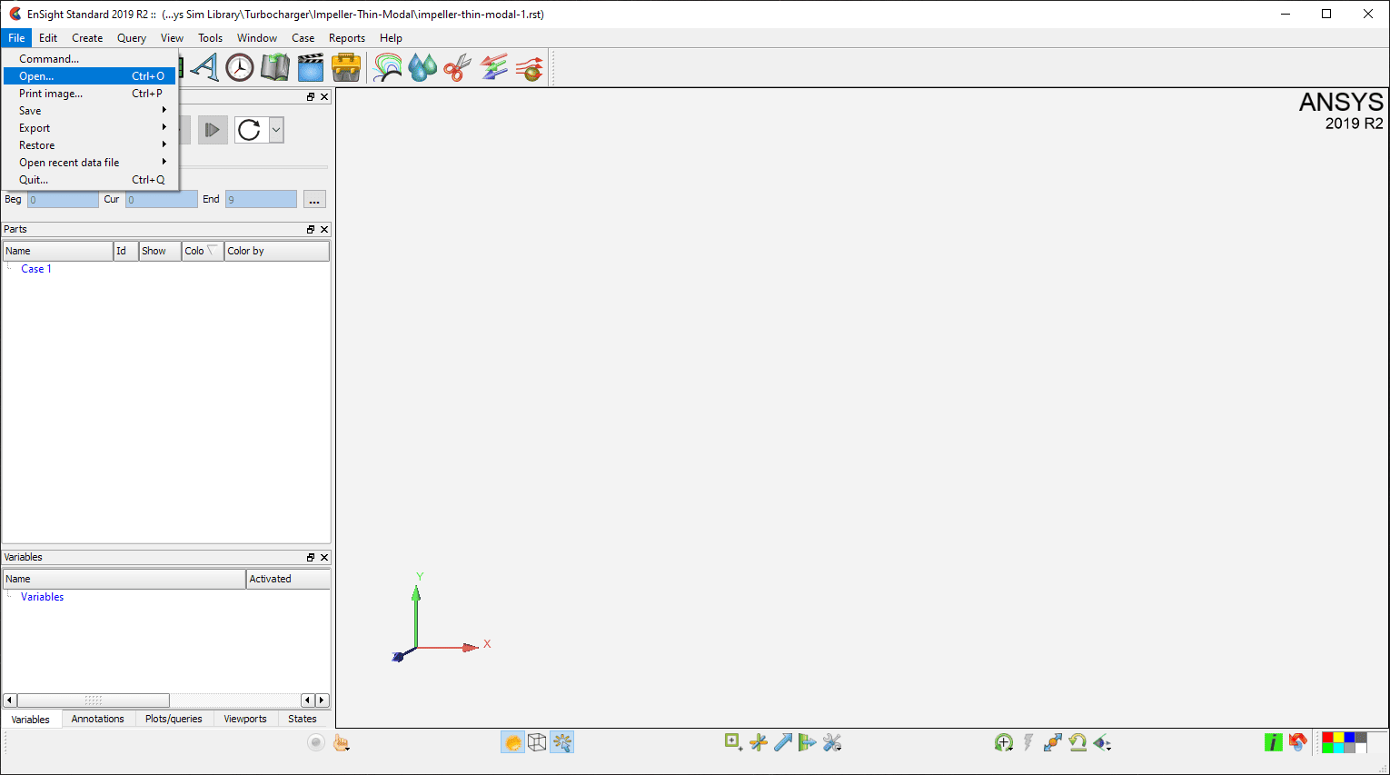
That brings up a blank session. To get started click File > Open

This will bring up a dialog box for specifying a results file. If you click on the “File type:” dropdown you will see the long list of supported files it can work with. Take a look while you are there and see if any other tools you use are listed. Of course, Ansys FLUENT and CFX are listed. This is first and foremost a CVD post-processor.
But the one we want is Ansys Results (*.rst *.rth *.rfl *.rmg). Chose that then go to the directory where you put your Ansys result file.

EnSight will read the file and put it in a Case. It will list the results as Part 0 under Case 1.

The left part of the screen shows what you have to work with, and the right shows your model. The “Time” control, circled in green, is where you specify what time, substep, or mode you want. The “Parts” control lets you deal with parts, which we really won’t use. And the “Variables” control, circled in orange, is how you specify what result you want to view.
We want to plot deflection, which is a vector. Click on the + sign next to Vectors, and you get a list of what values you can show. The only supported result for model analysis is Displacement__Vibration_mode. Click on that. Then hold down the right mouse button and select “Color Part” > All.

This tells the program to use that result to shade the part. You should now see your contour.
Our example is a modal result. If you use a structural result file, you will be able to plot the displacement vector, as well as many stress results under “Scalars”

Next, you will want to clean things up. Go to View and turn things on and off as you see fit. I like to turn off perspective, the Axis triad, and sometimes the legend.

You may notice the “Lighting…” option. If you really want to get fancy, you can specify various lights to get shadows and such. I like to add a spotlight above and slightly off-center from the part. You can waste a lot of time playing with lights, so try to avoid it if you can.

To pick which mode or timestep you want, use the “Time” control. Clicking on the step forward or step back buttons (triangle with a small rectangle at the base) steps you through the results on your file. Or you can drag the slider.
By default, EnSight shows an undeformed object. If you want to see the deflected shape, click on the part then on the “Displacement” icon above the graphics window. Select the vector result you want to use, displacement in this case.

Note, the default displacement factor may not be a good guess, change that till you get the amount of deflection you want.

These are only a few of the dozens of options available. But we can get most of what we need with these, so let’s look at saving the plot.
Saving your image
Now it’s time to get a rendered plot. Go to File > Export > Image

There is a lot to do in the “Save image” dialog. First, set the format (red circle.) I always use PNG. Then set the filename and path.

Expand the Advanced area and click “RayTrace the scene” (orange circle). Then you need to tell it how many pixels you want. Go big. You can always shrink it later.
Click OK and generate your plot. Check it out, things may be fine.
Leveraging Ray Tracing in Ansys EnSight
If you want to make the plot even better, go back to the Save image dialog and click “Raytrace settings…” and move the Quality slider all the way to the right. Do know that it can take a while to ray trace a large image with lots of surfaces.

And this is what you get. Click on the image to see it larger.

There is are many more options in this tool. Spend some time exploring these features to get even better plots:
- You can change the shading of the surface by double-clicking on the part in the “Parts” control and then setting the surface lighting parameters. To get there, click on advanced, scroll down, and expand General. I like to up shininess. Play with these to see what works best.

- You can also create multiple views in the same window. Right mouse clock in the graphics window and select “Viewports” and pick what you want. You can’t ray trace but you can still get output of multiple windows.

Here is what the output looks like, whithot ray tracing. Not bad.

- Sometimes you may want to make your part transparent. You can set that in the controls under General, where you can change the lighting.

And you get a very cool plot. I’m not sure when you would use it, but if you need it, it is handy. CFD users need this all the time.

The problem with this tool is that it has so many great features, you could burn a lot of time just changing things. But if you stick to the basics, you can take your plot to that next level for your website or brochure.
Plotting a single part in a multi-part file
There is one last detail to mention. What do you do if your model is an assembly but you only want to plot one part. EnSight treats a given RST file as one part. So you can’t really scope to just the part you want.
The solution is to open your RST file in Mechanical APDL and save out the parts you want to plot in a seperate result file. You do this with the APDL command: rsplit
Here are the steps:
- Get into APDL
- Use “set” to read the results file
- Select the elements you want as separate parts for plotting using standard APDL commands or the GUI.
- Create element components for them (cm,name,elem, or the GUI)
- Use rsplit to write an RST for each part: rsplit,all,all,cmname where cmname is the component name you created in step 4.
- This makes an rst file called cmname.rst. Now use this rst file for the above process
Let’s make a movie next
This post and the previous one focused on high-quality 2D plots. What if you want to show motion? Read on to the third post in the series to learn how to create outstanding videos in Ansys Mechanical – “3 – An update on outputting results in Ansys Mechanical: Making Videos“


