
Customizations developed using ANSYS ACT adhere closely to the user experience that is native to Mechanical and other Workbench apps. Obviously, this is to be expected, but sometimes it can be a little challenging to fit a particular workflow into the “tree object” plus “object properties” model. One way to broaden the available set of user experiences from which to construct a customized behavior is to use what are known as property controllers.
Property controllers are classes, which can be implemented either in C# or Python that are associated with a given property in the details pane of a given ACT object. These classes allow the programmer to specialize the functionality and behavior of the particular property to which they are associated. The association between a given property and its property controller is made in the ACT XML definition file. For this article, like most of the ones I write on ACT, I will be using C# as the implementation language.
The degree to which any given property can be specialized by a property controller is quite vast. Therefore, I won’t be able to touch on all of the possible combinations. However, I will demonstrate two that I have found particularly useful in various ACT apps I’ve written.
The first is a custom “select” controller that allows the user to pick one of a set of given Mechanical objects. For most customizations, perhaps the canonical example, is a select controller that allows a user to pick a particular coordinate system out of all of the defined coordinate systems in the model. Yes, there is a template for this that ships with Mechanical, but I will show a given implementation. Understanding how the controller works will enable you to apply the same technique to other object types, even other ACT objects within the same app.
The second is a way to “fly out” a dialog box that can contain additional custom controls, and that is “anchored” to the side of the given property box within the details pane. This is useful for scenarios when we can’t easily fit a particular data entry within a given property field. Tabular data is a prime example. Again, there are some templates for this in Mechanical, but understanding how to build it up from scratch will allow you to apply the same principles to more complex dialogs. This second example will be covered in a subsequent blog post.
Foundations
Before we dive into the individual examples above, let’s understand some of the basics of property controllers in general. First, how do we associate a given property controller class with a particular property. This is accomplished by using the “class” attribute in the property tag within the XML definition. So, here is an example from an extension XML file:
<property name="EngineAxis"
  caption="Coordinate System"
  control="select"
  class="PADT.PropertyControllers.CoordinateSystemSelectController">
  <attributes type_filter="cylindrical"/>
</property>
You can see that we’ve added a “class” attribute inside the property tag and set it equal to a fully qualified class name. All other property attributes are the same as with a typical property. In order for this to work, however, we will need to implement a class called “CoordinateSystemSelectController” in the PADT.PropertyControllers namespace.
You will also notice that there is a nested <attributes> tag inside the <property> tag. This can be used to pass additional configuration data to the controller as we will see. Clearly, in this case, the additional data is designed to constrain the types of coordinate systems that will be populated within the control.
Example 1: Coordinate System Select Property Controller
The method by which behavior is customized for a given property is by implementing overrides for a series of virtual functions defined on the property itself. These virtual functions allow us to hook into various points within the properties lifetime and operation. The names for these virtual functions correspond to the callbacks listed in the ANSYS help for the <property> tag in the ACT XML reference manual. The names are always lowercase. Common ones that I use are functions such as “onactivate”, “onshow”, “isvalid”,”value2string” and “getvalue”. Except for the “value2string” function, most of these are probably self-explanatory as to when they would fire. For this controller, I’ll demonstrate a few of these functions including when and how to use the “value2string”.
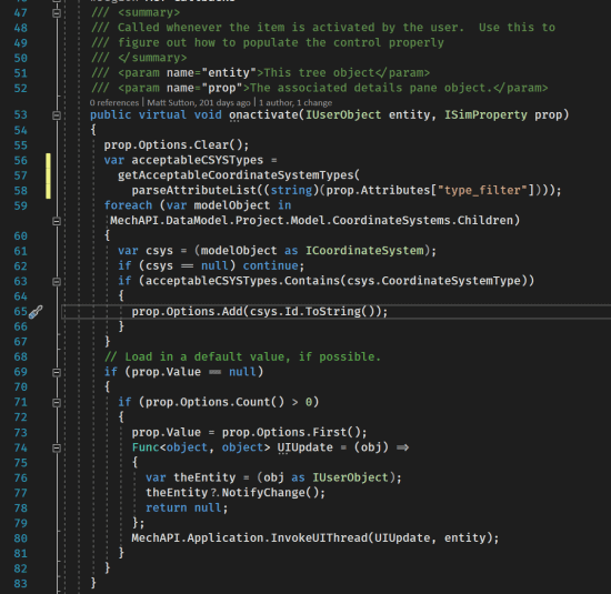
Let’s begin with the “onactivate” function. This function is called when the user “selects” or activates the property. So, within this function is a good place to populate the list of currently available coordinate systems. It is tempting to cache this list so that it doesn’t have to be recomputed. However, if the user deletes, or adds a coordinate system after we have cached the list, we would not display it as an option the next time they activated this control. Therefore, on each activation, we build up a list of available coordinate systems. Here is the code:

You can see the parameters to this function are parameter representing the “tree object” to which this property is a member of that object’s details pane, and a parameter representing this “property”. The second parameter might seem counterintuitive. You might think that we are subclassing the property itself and thus this parameter would be redundant. (i.e, it would be equivalent to the “this” object). However, we are not subclassing the property per say, but rather implementing a controller object that property itself makes calls against to modify its own behavior. Sounds convoluted, I understand, but my guess is that this is what allows us to specify all of this within the extension XML file. So, it’s a good thing.
Once we get into the function proper, on line 55 we clear out all of the items within this properties associated drop down control. Then, in lines 56-58 we figure out what are the enum constants that represent the types of coordinate systems (cylindrical, Cartesian, etc…) that we would like to present to the user. Note, our attribute “type_filter” could contain multiple types. Then, in lines 59-67, we iterate over all of the coordinate systems current defined in the Mechanical session and pick out the ones that are of the right type. We then add them to the “options” property of this SimProperty object. Note, however, that we don’t add the coordinate system objects themselves, but rather string representations of the object Ids. This is important. The reason we don’t add the name of the coordinate system is because names (or labels) in Mechanical are not required to be unique. You can create five coordinate systems and name all of them “Bob”, Mechanical doesn’t care and will treat them as unique. So, we need a unique attribute of the coordinate system to store in our list of options. The object Id is guaranteed to be unique. So, we store this instead.
The final bit of code in this function just makes sure to default select one coordinate system if the user hasn’t already selected one. That functionality is on lines 69-83. If the Value property is null, then the user (or this code) has not populated the select with a given coordinate system. So, if there are any coordinate systems that are appropriate we just find the first one and select it automatically. Note, if the user later changes this to a different CSYS and this function fires a second time, it will not overwrite their choice because the null check will fail on line 69. The reason for this behavior is because the extension for which this code was written made extensive use of a single cylindrical coordinate system in a number of different objects. Typically the user would add just this one coordinate system in addition to the default global Cartesian system. So, by adding this code, the user would not be required to select this coordinate system each time they added a new object, but rather, the tool would do it for them.
The next bit of code to examine is the “value2string” function, which is shown below:

You may recall from above that the data we store in the options property was a list of string representations of the various coordinate system Ids. Now, if we didn’t implement this function, when the user interacted with the drop down control what they would see would be a list of numbers. They might see a list like “42” “87” and “94”. Clearly, it’s not very intuitive as to which coordinate system these numbers may refer.
So, what the “value2string” function allows us to do is to transform the data that the property actually stores into a visual representation that is meaningful to the user. However, this is purely a stateless transformation. The actual data store in the property always remains the string representation of the object’s id. So, you can think of this function as sitting between the internal code that pulls a value out of the property, and the internal code that renders that value to the screen. In between these two calls, we have the opportunity to transform what gets rendered.
So, essentially what we do inside this function is parse the Id string back into an integer. If that’s cool, we then lookup the particular mechanical tree object that has this given Id. Finally, if everything is kosher with this object, we return the name of the object we looked up. If at any point something goes wrong, we just return an empty string.
Now, when the user interacts with the property controller, the will see a list of names corresponding to the coordinate systems of the appropriate type. If they sadistically named all of these coordinate systems the same name, then they will see a list with multiple entries of the same name. However, each one in the list is a unique coordinate system. How they figure out which one is the one they actually want is now their problem…
Finally, the last function we will look at is the “getvalue” function. As the “value2string” function made the experience of the end user more palatable, so too the “getvalue” function makes the experience of the developer more palatable. Essentially what it does is analogous to the “value2string” function, but rather than returning a string, it returns an actual coordinate system object that can be used in other places in the system. It looks like the following:

As you can see, it is very similar to the “value2string” object, but instead of returning a string, it returns the actual tree object itself. Note, you have to cast the return value at the caller site to the appropriate type, but meh… it’s still nice to have.
Finally, to see this property controller in action, I’ve taken a quick screen grab of the properties pane of an ACT object I’ve implemented. This is a little symmetry object that implements a homebrewed CPCYC, but you can see the coordinate system object.

That’s all for this post. Next time we’ll look at how to implement the flyout feature. Good luck with your ACT programming needs. Oh, and if you need some help, or ever want to have some ANSYS customization done for you, let us know. We do all sorts of customization work from more run of the mill type


