
In this article, I would like to introduce some new features added to the Ansys Electronics Solution 2020R2 release called SPISim. Since this is a new tool, I’ll focus on describing its capabilities as well as some possible applications.
What is SPISim?
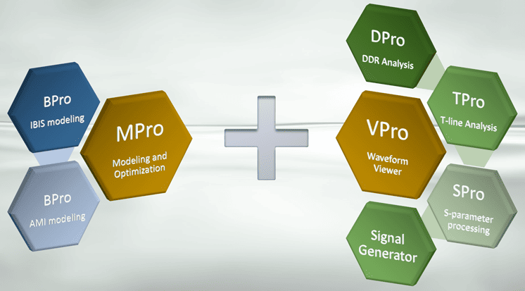
Signal, Power Integrity and Simulation (SPISim) focuses on system-level and on-chip SI/PI modeling, simulation, and analysis. The tool presents a variety of different features, which are split on separate modules shown below.

Let us look at each module individually and highlight the key functionality.
There are 2 main Modules VPro and MPro. All the other features (sub-modules) are split between these main two.
VPro Core
This is a versatile GUI for viewing waveforms. It supports a wide variety of formats including .tr0, .ac0, .ibis, .csv, .mat, .raw, .snp, .citi, and more. Besides simple viewing capabilities, VPro can also be used for waveform analysis:
- Overshoot and Undershoot (for Peaks and Valleys)
- Threshold Crossings
- Min/Max Peak-2-Peak
- Root-Mean-Square Value
- FFT, iFFT
- Correlation
- Pulse to PDA
Using the information about waveforms, this tool can also plot an eye diagram, perform simple correlations, and run measurements. The viewer also supports framework scripting on JavaScript, Ruby, TCL, etc.
DPro Unit (VPro Module)
DPro (short for DDR Pro) provides comprehensive DDR related post-processing analysis. Key functionalities of this tool:
- Batch mode of processing one or more waveform files
- Support of multiple receiver processing
- Built-in and customizable derating table and derating processing
- Built-in 100+ measurement functions for typical DDR signal analysis
- Results cross-probing and show problematic location automatically
The feature is organized in a wizard-like style. The user simply needs to fill out information in 6 tabs and click the ‘Run’ button. Overall, it is very intuitive to use, but like any new features, there is a learning curve for a new user.
TPro Unit (VPro Module)
It provides comprehensive transmission line related modeling, analysis, post-processing, and viewing capabilities. Here are several main functionalities offered by this add-on:
- Comprehensive stackup planner to model t-lines’ performance in different stackup configurations
- Advanced t-line modeling viewer for rapid analysis such as impedance, crosstalk, or propagation delay analysis
- A table viewer for RLCG frequency content
- What-if analysis for quick impedance/crosstalk calculation, and data processing, such as trimming and merging of frequency points
- Batch mode processing and measurements for one or more t-line model files, result is a plain .csv file ready for further modeling or analysis
This feature helps the user to run pre-layout ‘what-if’ analysis. Both ‘transmission line analyzer’ and ‘layer stackup planner’ give the user a flexible way of understanding potential design constrains and guidelines.
SPro Unit (VPro Module)
This module is similar to TPro in a sense of the capabilities. However, it is directed to view and analyze S-parameters instead of tabular transmission line data. Also, in contrast to TPro, this feature has a separate tab ‘S-Param’ with all the features listed there.
Here are major capabilities of SPro:
- Advanced s-parameter viewer for speedy analysis such TDR/TDR or PDA analysis
- Table viewer for frequency content; export s-parameter data to matlab .mat format and more
- 20+ advanced analysis functions such as mixed-mode conversion, cascading and renormalization
- Batch mode processing and measurements for one or more s-parameter files
- Support customizable s-parameter reporting generation for lab automation and beyond
Besides the conceptual similarities with the TPro, S-parameter’s waveform viewer based on VPro waveform viewer. Therefore, all operations available in VPro can also be found in S-parameter viewer.
Signal Generator Unit
This tool allows the user to generate a signal and use it in a future analysis. The generator offers wide variety of signal patterns (such as PRBS, Pulse, Sine, Square, Sawtooth etc) in combination with the PAM4 and NRZ modulation schemes. The user needs only to specify parameters for the signal and then create it.
This simple, but very powerful feature helps to save time for the engineer.
MPro Core
By definition, MPro is a modeling unit, which helps the user to work with the data. However, modeling can mean different things. The main advantage of MPro is providing the user with the simple environment for data manipulation. Here are all main functionalities of this core module:
- Table data processing: combine, extract, summarize statistically, etc
- Plan sampling with design of experiments, full factorial, Monte Carlo, etc
- Simulate or collect data using customizable scripts, supporting multi-CPU/multi-thread
- Visualize data in statistical, 2D or 3D plots
- Model data using response surface modeling, neural network (feed forward and radial basis), etc
- Optimization using linear, nonlinear, or genetic algorithm methods
BPro IBIS and AMI Unit (MPro Module)
BPro is one unit, however in this description I have purposefully separated it into two – BPro IBIS and BPro AMI, because the functionality of BPro is very broad. It is easier to focus on a one thing at a time.
Generally, BPro brings comprehensive IBIS related modeling, analysis, post-processing, and viewing capabilities to user. In more detail:
- Has an inspector to view IBIS model’s textual content and visualize various waveform/current table easily. Tool also allows manual editing of model data with a simple mouse click and drag
- Built-in advanced IBIS model generation flow from either scratch or existing simulation data. Tool will guide user from modeling setup, spice decks generations, simulation, modeling, syntax checking with golden parser, validation to final figure of merits (FOM) reporting
- Support batch mode generations of performance reports for one or more model files. Results are in .csv file format and can be used for further analysis
- IBIS model generation from Spec. or data sheet without performing any simulation. Generated model will also have two sets of waveforms under different loading conditions
Under ‘IBIS’ menu tab, the user will find separate sets of commands for both IBIS and AMI, as well as commands for IBIS-AMI in general.
Summary
This new addition to Ansys Electronics Solution brings a very wide variety of features to engineers. All Waveform Viewer, Signal Generator, IBIS-AMI modeling, DDR analysis, Data optimization, and Transmission line planner are united under one tool – SPISim. We can launch this tool either from within Ansys 3D Layout or SIwave, and, in 2020R2, is accessible through the Electronics Enterprise license.
Here is an overview of the SPISIm functionality:

Besides developing the help documentation and video demos, SPISim engineer team provides users with the detailed information about the tool in their blog – http://www.spisim.com/blogs/blog-articles-index/ and helps to fill out the technical ‘gaps’ by sharing the reference material – http://www.spisim.com/products/ami-spisims-ibis-ami/academic-serdes-ami-reference/
If you would like more information related to this topic or have any questions, please reach out to us at info@padtinc.com.


