
It is no mystery that I love my Subaru. I bought it with the intention of using it and I have continually made modifications with a focus on functionality.
When I bought my roof crossbars in order to mount ski and/or bike racks, I quickly realized I needed to get a fairing in order to reduce drag and wind noise. The fairing functions as designed, and looks great as well. However, when I went to install my bike rack, I noticed that the fairing mount was in the way of mounting at the tower. As a result, I had to mount the rack inboard of the tower by a few inches. This mounting position had a few negative results:
- The bike was slightly harder to load/unload
- The additional distance from the tower resulted in additional crossbar flex and bike movement
- Additional interference between bikes when two racks are installed

These issues could all be solved if the fairing mount was simply inboard a few more inches. If only I had access to the resources to make such a concept a reality…. oh wait, PADT has all the capabilities needed to take this from concept to reality, what a happy coincidence!
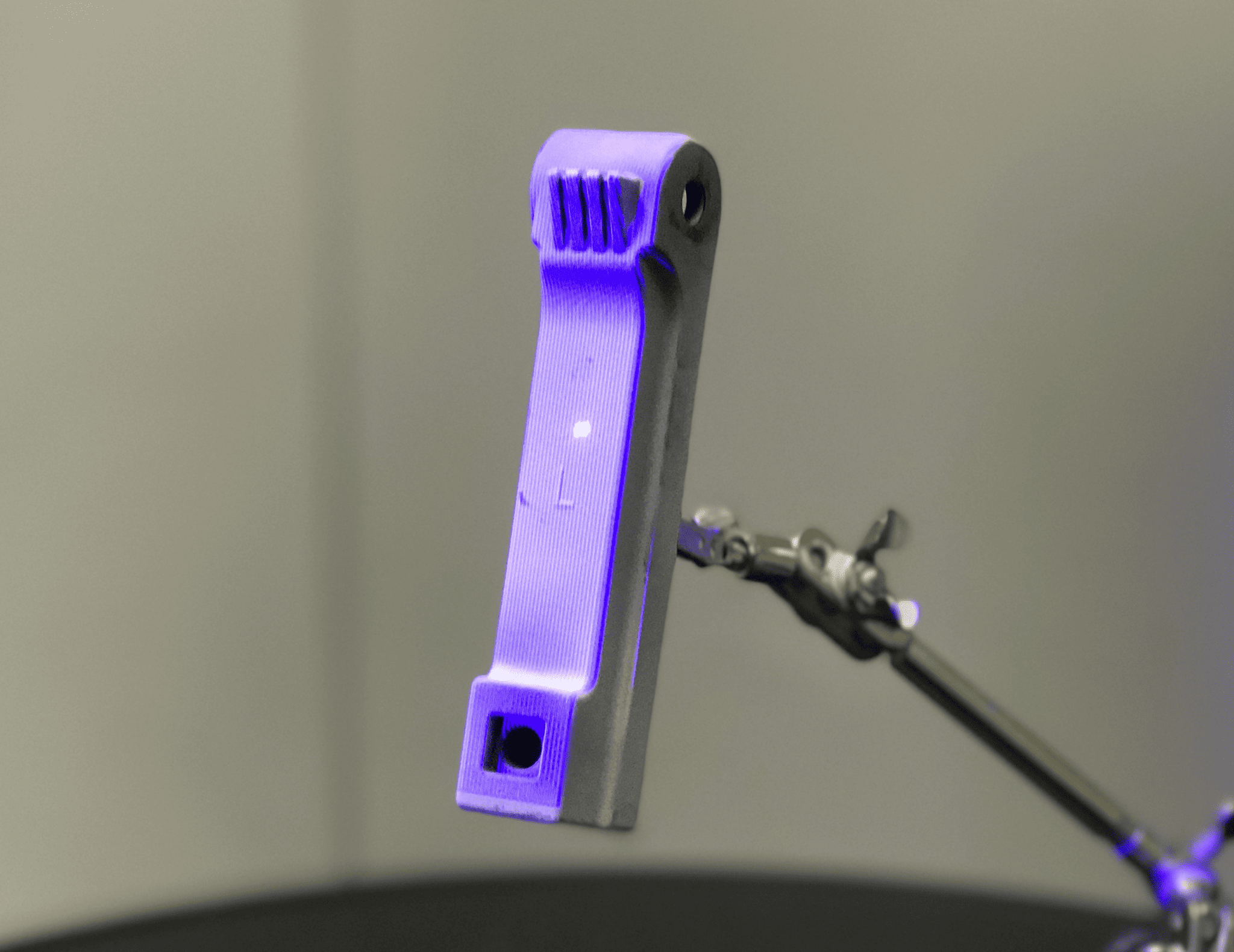
First, we used our in-house ZEISS Comet L3D scanner to get a digital version of the standard left fairing mount bracket. The original bracket is coated with Talcum powder to aid in the scanning process.

The output from the scanning software is a faceted model in *.STL format. I imported this faceted CAD into ANSYS SpaceClaim in order to use it as a template to create editable CAD geometry to use as a basis to create my revised design. The standard mounting bracket is an injection molded part and is hollow with the exception of a couple of ribs. I made sure to capture all this geometry to carry forward into my redesigned parts, which would make the move to scaled manufacturing of this design easy.


Continuing in ANSYS SpaceClaim, as it is a direct modeling software instead of traditional feature-based modeling, I was able to split the bracket’s two function ends, the crossbar end and fairing end, and offset them by 4.5 inches, in order to allow the bike rack to mount right at the crossbar tower. I used the geometry from the center section CAD to create my offset structure. A mirrored version allows both the driver and passenger side fairing mount to be moved inboard to enable mounting of two bike racks in optimal positions. The next step is to turn my CAD geometry back into faceted *.STL format for printing, which can be done directly within ANSYS SpaceClaim.


After the design has been completed, I spoke with our 3D printing group to discuss what technology and material would be good for these brackets, as the parts will be installed on the car during the Colorado summer and winter. For this application, we decided on our in-house Selective Laser Sintering (SLS) SINTERSTATION 2500 PLUS and glass filled nylon material. As this process uses a powder bed when building the parts, no support is needed for overhanging geometry, so the part can be built fully featured. Find out more about the 3D printing technologies available at PADT here.

Finally, it was time to see the results. The new fairing mount offset brackets installed just like the factory pieces, but allowed the installation of the bike rack right at the tower, reducing the movement that was present when mounted inboard, as well as making it easier to load and unload bikes!!


I am very happy with the end result. The new parts assembled perfectly, just as the factory pieces did, and I have increased the functionality of my vehicle yet again. Stay tuned for some additional work featuring these brackets, and I’m sure the next thing I find that can be engineered better! You can find the files on GrabCAD here.


