
As systems become more complex, the introduction and adoption of detailed Multiphysics / Multidomain tools is becoming more commonplace. Oftentimes, these tools serve as preprocessors and specialized interfaces for linking together other base level tools or models in a meaningful way. This is what Ansys Sherlock does for Circuit Card Assemblies (CCAs), with a heavy emphasis on product reliability through detailed life cycle definitions.
In an ideal scenario, the user will have already compiled a detailed ODB++ archive containing all the relevant model information. For Sherlock, this includes .odb files for each PCB layer, the silkscreens, component lists, component locations separated by top/bottom surface, drilled locations, solder mask maps, mounting points, and test points. This would provide the most streamlined experience from a CCA design through reliability analysis, though any of these components can be imported individually.
These definitions, in combination with an extensive library of package geometries, allow Sherlock to generate a 3D model consisting of components that can be checked against accepted parts lists and material properties. The inclusion of solder mask and silkscreen layers also makes for convenient spot-checking of component location and orientation. If any of these things deviate from the expected or if basic design variation and optimization studies need to be conducted, new components can be added and existing components can be removed, exchanged, or edited entirely within Sherlock.

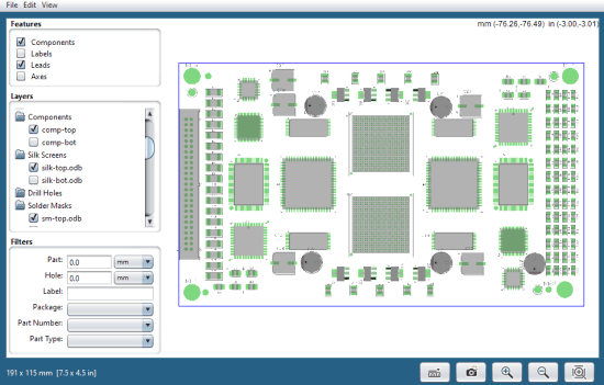
Figure 1: Sherlock’s 2D layer viewer and editor. Each layer can be toggled on/off, and components can be rearranged.
While a few of the available analyses depend on just the component definitions and geometries (Part Validation, DFMEA, and CAF Failure), the rest are in some way connected to the concept of life cycle definitions. The overall life cycle can be organized into life phases, e.g. an operating phase, packaging phase, transport phase, or idle phase, which can then contain any number of unique event definitions. Sherlock provides support for vibration events (random and harmonic), mechanical shock events, and thermal events. At each level, these phases and events can be prescribed a total duration, cycle count, or duty cycle relative to their parent definition. On the Life Cycle definition itself, the total lifespan and accepted failure probability within that lifespan are defined for the generation of final reliability metrics. Figure 1 demonstrates an example layout for a CCA that may be part of a vehicle system containing both high cycle fatigue thermal and vibration events, and low cycle fatigue shock events.

Figure 2: Product life cycles are broken down into life phases that contain life events. Each event is customizable through its duration, frequency, and profile.
The remaining analysis types can be divided into two categories: FEA and part specification-based. The FEA based tests function by generating a 3D model with detail and mesh criteria determined within Sherlock, which is then passed over to an Ansys Mechanical session for analysis. Sherlock provides quite a lot of customization on the pre-processing level; the menu options include different methods and resolutions for the PCB, explicit modeling of traces, and inclusion or exclusion of part leads, mechanical parts, and potting regions, among others.

Figure 3: Left shows the 3D model options, the middle shows part leads modeled, and right shows a populated board.
Each of the FEA tests, Random Vibration, Harmonic Vibration, Mechanical Shock, and Natural Frequency, correspond to an analysis block within Ansys Workbench. Once these simulations are completed, the results file is read back into Sherlock, and strain values for each component are extracted and applied to either Basquin or Coffin—Manson fatigue models as appropriate for each included life cycle event.
Part specification tests include Component Failure Analysis for electrolytic and ceramic capacitors, Semiconductor Wearout for semiconductor devices, and CTE mismatch issues for Plated Through-Hole and solder fatigue. These analyses are much more component-specific in the sense that an electrolytic capacitor has some completely different failure modes than a semiconductor device and including them allows for a broad range of physics to be accounted for across the CCA.
The result from each type of analysis is ultimately a life prediction for each component in terms of a failure probability curve alongside a time to failure estimate. The curves for every component are then combined into a life prediction for the entire CCA under one failure analysis.

Figure 4: Analysis results for Solder Fatigue including an overview for quantity of parts in each score range along with a detailed breakdown of score for each board component.
Taking it one step further, the results from each analysis are then combined into an overall life prediction for the CCA that encompasses all the defined life events. From Figure 5, we can see that the life prediction for this CCA does not quite meet its 5-year requirement, and that the most troublesome analyses are Solder Fatigue and PTH Fatigue. Since Sherlock makes it easy to identify these as problem areas, we could then iterate on this design by reexamining the severity or frequency of applied thermal cycles or adjusting some of the board material choices to minimize CTE mismatch.

Figure 5: Combined life predictions for all failure analyses and life events.
Sherlock’s convenience for defining life cycle phases and events, alongside the wide variety of component definitions and failure analyses available, really cement Sherlock’s role as a comprehensive electronics reliability tool. As in most analyses, the quality of the results is still dependent on the quality of the input, but all the checks and cross-validations for components vs life events that come along with Sherlock’s preprocessing toolset really assist with this, too.


