It is a fact. Microsoft Excel is the most used engineer tool in the world. If you are like me, you do everything you can’t do in ANSYS in Excel. And a lot of the time you wish you could talk directly from Excel to ANSYS – and in the day many of us wrote kludgey VB Macros that would write APDL scripts run ANSYS MAPDL in the background. In the past couple of releases our friendly neighborhood ANSYS developers have added a lot of different ways to work with Excel: saving tables to a file, Python scripting to talk to Excel, and an Excel System. I remember reading about these things as they came out, even wrote about how cool they were, but I never had the opportunity to use them.
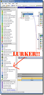
Then, last week, I noticed an Excel icon just sitting there in the toolbox, mocking me, taunting me to use it.
So I dragged it out on my project page and tried to use it… and got no where. My assumptions were not valid, it didn’t work the way I expected because, it turned out, I was not thinking about how it fit into the project correctly. So I backed up, actually read the help (gasp!) and after a experimenting got it to work, I thought. Then I talked to some folks at ANSYS, Inc. and they reminded me of what this is: an Excel Solver System. It is not a tool that lets you “drive” your project from Excel. It lets you use Excel to calculate values.
This posting is a summary of what I learned. And as I was working through it I thought it would be good to also cover the python interface to Excel and how to save tabular information to Excel. These will be covered in future articles (hence this being Part 1).
What You Need to Know
As I said above, my problem was that I was thinking about how Excel fit into my project all wrong. The first thing you should do is read the help on the Excel System. The best way to find it is type excel into search. The item with the most hits will take you to the article for component systems, then click on Microsoft Office Excel. (I wish I could just put a link in… grumble… grumble… ).
To use the Excel system you do the following:
- Add the System to your project
- Make a spreadsheet and use range names to identify parameters
- Attach an Excel spreadsheet
- Edit the system and tell the program which parameters are input and which are output
- Go into the parameter manager and hook up any derived parameters you want to pass to Excel and use any of the Excel parameters with other parameters as needed
- Tell ANSYS to run a VB macro (if you want)
- Update your project or Design Points
We will go through the process in detail but first, a few things you should know:
- The system kind of looks and feels like the parameter manager in Workbench, but it is not. You have to think of Excel as a “solver” that feeds parameters from and to the parameter manager.
- I struggled with this because I thought of output parameters as values calculated by Workbench and input parameters as ones that come from Excel, but the opposite is true.
- Excel Input Parameter: A value calculated in Workbench parameter manager
- Excel Output Parameter: A value calculated in Excel
- You need to get your head around this or you will get stuck like I did. The example should help.
- Parameters that come from DesignModeler are dimensionless in the parameter manager.
- This one really held me up for a while. If you assign a parameter from Excel that has a unit to drive your geometry in design modeler, you get an error.
- The solution is to make sure that you DO NOT use units on Excel parameters that you get or pass to DesingModeler
- When you attach the Excel file to your Excel system on the project page Workbench copies the Excel file to your project and buries it in dpall\XLS.
- You will get burned by this if you go to your original excel file, edit it, then try and update your project. Your changes will not show up. That is because it is not linked to the original file, it is linked to a copy stored in that XLS directory.
- Once you have linked a file you should exit Excel then open the file by RMB on the Excel system and choose “Open File in Excel” (see below for more on this whole process)
- I recommend that you start buy making your Excel file, save it with the name you want in the C:\Temp directory, attach that file, close Excel, then open from Workbench.
- Now you have a file to add your stuff to and you don’t have to worry about having an earlier version lurking around.
- An important side effect of this is if you delete your system, it deletes your Excel file! So make sure you make a copy or do a save as before you remove the Excel system
- To get changes in Excel to show up in your project, you need to save the file AND refresh/reload.
- Making a change to he Excel file will put the system out of date. A refresh on the project page or a reload on the “Edit Configuration” page will update things.
- The parameter names in Excel are case sensitive. So whatever your prefix is in the system properties (WB_ by default) you need to have the same in your Excel spreadsheet for range names.
- To get a full update, including running any macros and doing any calculation, you have to update the system. This is kind of obvious, but I kept forgetting to do it.
- Your Excel file will not update if you use RSM. Make sure your default for updating your project is to run local and, that if you are using design points, you set that update to run in the foreground.
- The easiest way to check and change this is to click on the parameter bar and view its properties. Under Design Point Update Process set Update Option to Run in Foreground.
- If you want to have your Excel file define both input and output parameters for the same ANSYS simulation, workbench sees that as a “cyclic dependency” and will not let you do it.
- Although annoying at first glance, it kind of makes sense. If you feed a value to Excel and then Excel calculates a new value that effects your ANSYS model, you need to update the ANSYS model, which will change the value that gets passed into Excel, which will change the value that gets passed out which changes your ANSYS model, which… and so it goes in a loop. This is considered a bad thing.
- This goes back to the fact that Excel should be used as a solver, not as ‘”driver” of you simulation.
- If you do want to drive your analysis from Excel, you’ll need to do some scripting. We’ll cover that in a future article.
The Process
I started this article with a really cool valve demo model. Then found that it was just too slow and a pain to work with for showing how the Excel system works. So I went back to my second favorite type of model, a simple “tower of test.” (my favorite is a FPWHII – flat plate with a hole in it). You can download the project here.
Add the System to Your Project
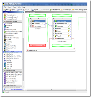
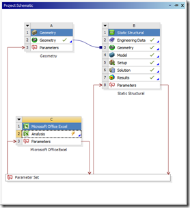
Like every other system in Workbench, you simply drag from the toolbox to the Project Schematic. Notice how the green “drop zones” are all empty spaces. You can’t drop it on an existing cell in a system because there is no dependency between other systems and an Excel system. The Excel system is connected through parameters, which we will see in a bit.
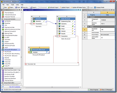
Once you have dropped it onto the schematic, click on the Top cell (C1 in this case) and check out the properties (RMB Properties if the window is not already open). From the properties you can see the system ID (XLS) and you can specify an Analysis Type. You can leave it blank or type in something like “Home Grown Optimization.”
Then click on the Analysis cell (C2 in this case) and look at the properties. They are shown here:
One key thing to note is that the directory where the Excel file will be copied is shown. I did this once already on this project so it made a XLS-1 directory. If I did it again, I’d see XLS-2, etc… In fact, by the time I got done with this article and trying all sorts of things, it ended up in XLS-8.
The most important option under Setup is the “Parameter Key” Any Excel named range that begins with this string will get read into the parameter manager. If you make it blank, all the named ranges will come in.
Make a Spreadsheet and Use Range Names to Identify Parameters
Now you need to create your spreadsheet. You need to plan ahead here a bit. Figure out what parameters you need Excel to get from your models and what parameters you want to send back. Come up with good names because that is what gets passed to Workbench.
What happens when you attach a file is that Workbench goes to the Excel sheet and steps through all the named ranges in the file. If it finds one with a name that starts with the filter value, it grabs the first value in the range as the parameter value and then grabs the second as the units. If your range is bigger, it just ignores the rest.
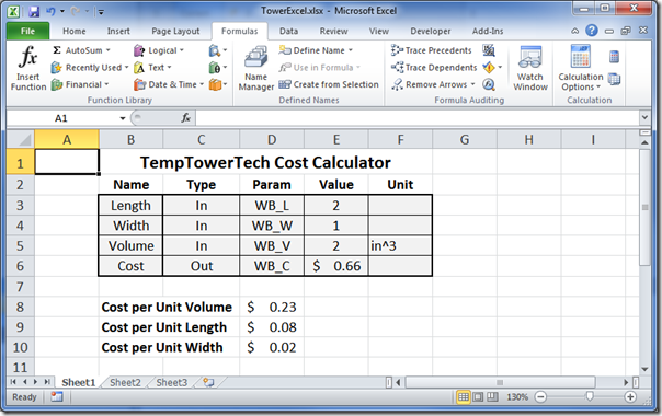
So this tells us that we need to create a range that has at least one cell, or two if units are important. For our simple example we will be calculating costs and outputting that using the input Volume, Length and Width. There is a formula in the cost cell that multiples those values times pre-set costs per unit volume, length and width and sums them up to get a cost.
So the laziest thing you can do is select a cell and name it.
But it will help you and others if you actually make a table that has a descriptive name, the parameter name (WB_ should be your default), the value for that parameter, and the units, if any. Note that for an input parameter you can just set the value to zero to get started. Here is what the tables look like for our example:
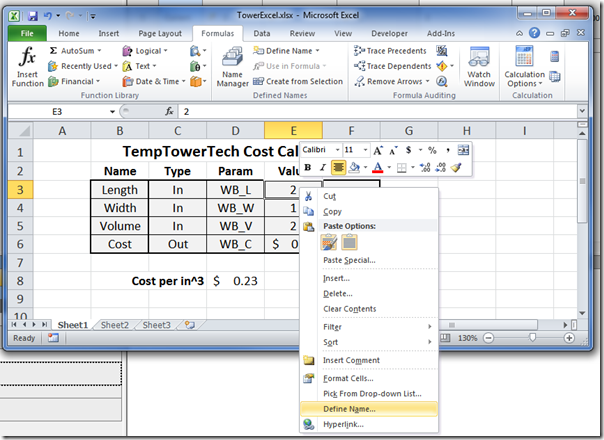
To create a range you select the value and units for a given parameter, hold down the Right-Mouse-Button (RMB), and Select “Define Range”
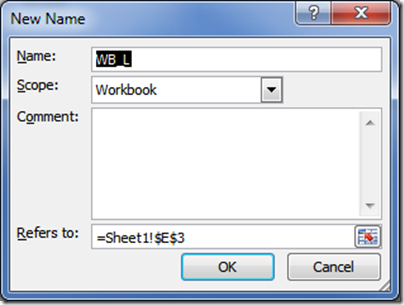
A cool thing that Excel does is to use the value just to the left of the range as the default name of the range. So by creating the table you save yourself some typing. Or, if you don’t use a table, just type in the name you want .
Now just click OK and you have a named range. You can repeat this for each range, or you can get fancy and use the fact that your data is in a table, with the parameter name to the left, to quickly generate all the ranges at once.
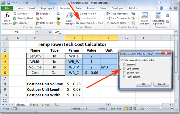
To do this, select the WB Param, value and unit columns. Then go to –>Formulas –> Defined Names –> Create from Selection. When the dialog box pops up make sure only “Left column” is checked. Click OK.
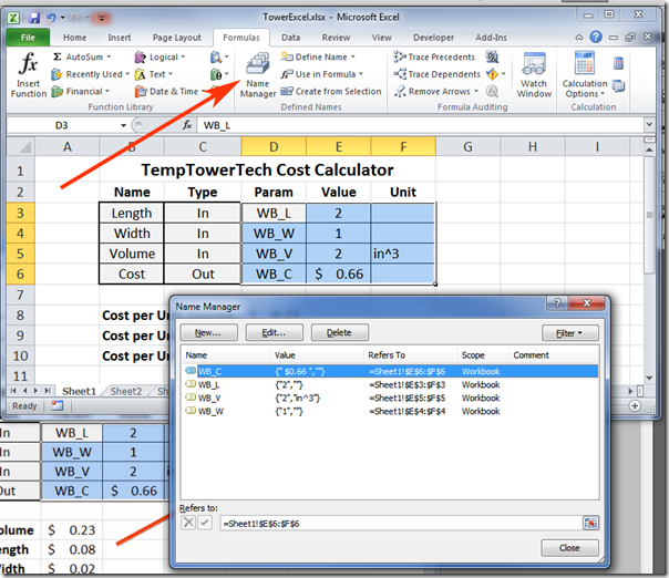
In one fell swoop you created all your named ranges. To see, edit, and delete ranges, regardless of how they were created, go to Formulas –> Defined Names –> Name Manager.
Take some time to look at this and understand it. When you are debugging and fixing stuff, you will use this window.
Now you have an Excel file that Workbench will like! Time to attach it. Save it (I recommend to save to temp so you don’t get it confused with the copy that Workbench will make).
Attach an Excel Spreadsheet
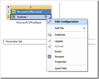
This is the easiest step. Simply RMB on the Analysis cell in the system and browse for the file.
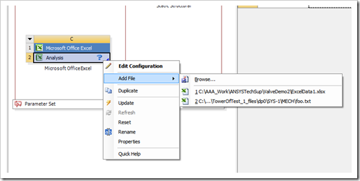 Now your Analysis cell has a lightning bolt, update to have it read the file and find parameters. If you have your parameters set up wrong, such that you don’t have any named ranges with the specified prefix, it will generate an error but will still attach the file.
NOTE: If you get some weird errors “Unexpected error…” and “Exception from HRESULT:…” when updating your Excel system, check your Excel file. Odds are you have an open dialog box or the file is somehow locked. The error generates because Workbench can’t get Excel to talk to it.
Edit the System and Tell the Program Which Parameters are Input and Which are Output
Although you have a green check mark, you will notice that your system is still not connected to your parameters, and therefor it is not connected to the rest of your model. The way to fix this is to RMB->Edit Configuration. Double-clicking on Analysis also does the same thing.
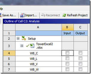
This puts you in Outline Mode. You should be familiar with this mode from the Parameter Manager or Engineering Data.
Take some time to explore this outline. Notice the setup cell, where you have access to the system properties. Then it’s child, the Excel file. Click on it to the properties for the file connection. Under that is the important stuff, the parameters.
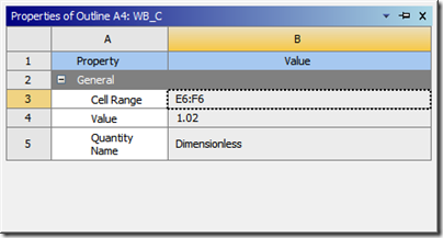
If you did everything correctly, you will see all of your parameters in alphabetical order. If you click on one, you will see the properties. Here they are for the cost value:
It shows the range, the value and units (C column) and the Quantity name. Workbench guesses by units. So PSI comes in as pressure by default. If it is a stress, you need to change it here.
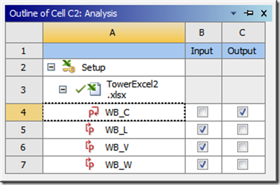
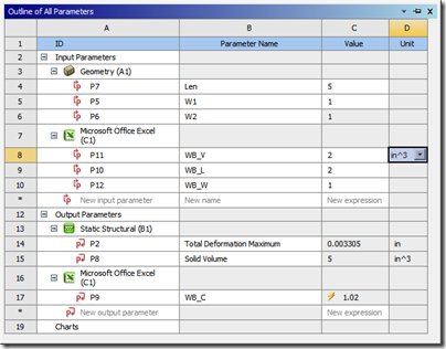
But your main task right now is to tell Workbench which of these parameters you want passed to the parameter manager, and what type of parameter, input or output, they are. Here is where I get screwed up. Because an input parameter in the parameter manager is an output parameter here. Remember, the Excel system is a solver that takes in parameters from the parameter manager and send back values to drive your models. So in our example, all the dimensions and the volume are passed from the parameter manager TO excel, so they are input. The cost is passed from Excel to the Parameter manager so it is output.
Now you have hooked up your Excel system. Click on the “Return to Project” at the top of the window and you will go back to the project schematic and see that a Parameters cell has been added to the system and it has been attached to the parameter bar.
Go Into the Parameter Manager and Hook Things Up
Although the Geometry and Mechanical systems are connected through the parameters to the Excel system, no relationships exist. We need to assign some values to our Excel parameters.
This is what our test model looks like before we do this:
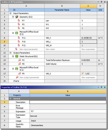
Our goal is to have the parameters in the first column below to drive those in the second:
| Driving Parameter | Driven Parameter |
| P7: Len | P10: WB_L |
| P5: W1 | P12: WB_W |
| P8: Solid Volume | P11: WB_V |
I tried to just click on the value in value column (C) and change the value from the number it is to the parameter name it should be but that does not work. Because the parameter is set as a constant. So, you need to click anywhere on the row for the parameter you want to set, then go down to the Properties window and change the Expression to the Parameter ID you want to change. This changes the Expression to be an equation and the Expression Type to be Derived:
That is it. You now have Excel in your project as a solver. Update your project and the cost will be calculated and presented as a parameter for optimization, DOE studies or whatever you want.
Tell ANSYS to run a VB macro (if you want)
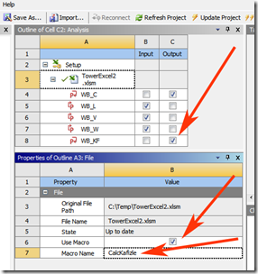
One really cool feature is that you can tell the program to run a VB macro on an update. What you do is go to your system, click on Analysis then RMB-> Edit Configuration. Then click on the file cell (A3). The property area now shows info on your file, and has a Use Macro row at the bottom. Click on the checkbox and a Macro Name row will popup. Enter the name of a macro in your spreadsheet and you are off.
Here is a silly example where I use a macro to calculate a value. For the example I put in the well known equation for deriving the Kafizle of a system:
- Create a new row in my table for the Kafizle value to go in
- Create a name WB_KF for the value
- Write my macro (don’t laugh):
Sub CalcKafizle()
Range(“E7”) = Rnd(1) + Cos(Range(“E5”).Value)
End Sub - Save my sheet and KABOOM. I now need to save it as an xlsm, not xlsx! I didn’t think about that!
- This means my Excel connection wont’ work. So you have to delete your system and start again with your macro file. So plan ahead! I’m glad I did this silly example rather than running in to it on a real problem.
- Once everything is right again, go into the outline for the excel system and make that new parameter (WB_KF) an output parameter.
- Then click on the File (A3) and go to the properties window and click on the Use Macro checkbox
- Put the macro name into the Macro Name field
Now you can run you project, and every time you do, the program will calculate a new cost and Kafizle value. This of course begs the question, what are the proper units of Kafizle? Here is the Design Point table:
Thoughts and Conclusions
I started this effort thinking I would drive my model from Excel, basically replacing the Parameter Manager with Excel. But that does not work because Excel doesn’t know enough about your project to handle the dependencies that can really cause problems if you don’t solve in the correct order. So once I figured that out I found some pretty good uses. Here are some other ideas for how to use the Excel System:
- Do additional post processing on result values
- Use formulas or lookup tables to calculate loads.
- Just make sure that the values you take from your ANSYS model into Excel (inputs) are also input parameters in the parameter manager.
- Use tables and lookups to calculate input values for an analysis
- A good example would be a “family of parts” application where you put in a part number and Excel does a vlookup() on a table that has all the input parameters listed by part number.
- To include results from an ANSYS analysis in a system model you have in Excel.
- You still have to force the update on the ANSYS side, which is not the ideal way to run a system model, but it may be easier than writing scripts and hooking it up that way.
This is a new feature at R13 and it can be a bit “touchy.” Especially if you are rooting around in it like a Javalina rooting around in your flower bed (Arizona reference). If you do something really crazy it can loose its way and start generated errors. I found the best solution at that point was to save a copy of my Excel file, delete the system, and start over.
This took a lot longer than I thought to write, but the Excel System does a lot more than I thought. I think as we all start thinking about how to use this tool, people will come up with some pretty cool applications.

