
Back “in the day” when we rode horses into work as Finite Element Analysis Engineers, we had somewhat limited compute capacity. 70,000 elements was a hard and fast limit. But we still needed accurate results with local refinement in areas of concern. The way we accomplished that was with a process called submodeling where you make a refined local model just of the area you care about, and a coarse mesh that modeled the whole part but still fit on the computer. The displacement field from the coarse model was then applied as a boundary condition on the refined model.
We called the refined model a zoom model or a submodel. It worked very well for many years. Then computers got bigger and we just started meshing the heck out of those areas of interest in the full part model. And in many cases that is still the best solution for an accurate localized stress: localized refinement.
Submodeling is one of those “tricks” in stress analysis that used to be used all the time. But until recently it was a bit of a pain to do in ANSYS Mechanical so it fell out of use. Now, the process of doing submodeling is easy, efficient, and accurate. The purpose of this posting is to introduce the concept to newer users who have not used it before, and show experienced (old) users how much easier it is to do in ANSYS Mechanical vs. Mechanical APDL.
What is Submodeling?
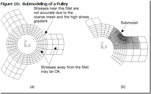
The best description of submodeling is the illustration that has been in the ANSYS help system, in one form or another, for over 25 years:

The basic idea is that you have a coarse model of your whole part or assembly. You ignore small features in the mesh that don’t have an impact on the overall response of the system – the local stiffness does not have influence on the strain beyond that local region. You then make a very refined model, the submodel, of the region of interest. You use the displacement field (and temperature if you have a temperature gradient) from the coarse model and apply it to the submodel as a boundary condition to get the accurate highly-refined response in the area of interest.
The process is based on St. Venant’s principle: “… the difference between the effects of two different but statically equivalent loads becomes very small at sufficiently large distances from load.”
 |
An aside: What a cool name this guy had: Adhémar Jean Claude Barré de Saint-Venant. To top it off he was not just a mathematician, but he was given the title of Count as well… a count mathematician. And, I have to say, I have serious beard envy. He had some very nice facial hair, I can’t even grow thick stubble. |
Anyhow, what he showed was that if you are looking at the stresses in a part far away from where loads are applied, how those loads are applied does not matter. So we can replace the forces/pressures/etc… from our course model as an equivalent static deflection load and the stress field will be the same.
The way this is done in a Finite Element model is you determine what faces in your submodel are “inside” your course model. These are called the cut boundary faces and the nodes on those faces are the cut boundary nodes. and you apply the displacement field from the coarse model onto the nodes
The most common use is to add mesh refinement in an area without having to solve the whole model. Another common usage is to actually mesh small features like fillets, holes, and groves that were left out of or under-meshed in the full model. It can also be used to capture material non-linearities if that behavior is highly localized.
But probably the most beneficial use today is to study the parametric variation of small features like the size of a fillet or a hole. If changing the size of such features does not change the overall response of the system, then you only need to do a parametric study on the submodel – as the guy with the great beard proved, if the static load does not change with your geometric variations, you don’t have to look at the whole structure.
And don’t forget the new crack growth capabilities. You will probably want to do that on a submodel around your crack and not on your whole geometry.
Here is a more modern version of the original example geometry:

The red highlight shows the cut boundaries. this is where you need to apply the displacement field.

This is the nasty coarse mesh. Now if you were modeling a single part, you would just mesh the fillets and be done with it. But assume this is in a large assembly.

The Submodel. Nice elements in the key area.
You can even set up the radius as a parameter and do a study, where only the Submodel is modified and updated.

The Process
The process is fairly simple:
- Make and solve your full model
- Make a geometry model of the area you want a submodel in
- Attach the submodel to the engineering data and solution of the full model
- Set up and solve the submodel
Before we get started, here is a ANSYS 14.5 archived project for both models we will discuss in this posting: PADT-Focus-Submodeling-2013_08_14.wbpz
For the sample geometry we showed above, the system looks like this:

When you go into ANSYS Mechanical for the sample model, you have a new model branch:

When you first get in there, the branch is empty, you have to insert Body Temperature and/or Displacement:

The Details for the Displacement object are as follows:

There are a lot of options here. It is basically using the external load mapper to map the displacements. Consult the help and just play around with the options to understand them better. In most cases, all you need to do is specify the faces that you want the displacement field applied to for the Scope section.
A cool feature is that once you have specified the faces, you can “Import Load” and then view them by clicking on the object. Graphics Control –>Data = All shows vectors. Total/X/Y/Z shows the applied displacement field as a contour:


Now you just need to make sure your Submodel is set up correctly, you have the mesh you want, and any other loads that are applied directly to the Submodel are the same as the loads in the full model (see next section). Run and you get your refined results.
Here is that same process with a more realistic model of a beam with a tube welded on it. The welds are not modeled in the full model and the fillets in the beam are very coarse.
So here is the geometry. Imagine that these two parts are actually part of a very large assembly so we really can’t refine them the way we want.

This is what the systems look like. Note that the geometry comes from one source. I made the submodel in the same solid model in DesignModeler and just suppress the parts I don’t want in each Mechanical model.

The loading is simple. I fix one end and put a force on the top of the tube.

And here is my coarse mesh. I could probably mesh the tube with a lot more elements, especially along the axis.

The results. Not too useful from a stress standpoint. Deflections are good, but the fillet is missing and beam is too coarse.

So here is the submodel. All the fillets are in there and it is just the area around the connection.

I used advanced meshing to get a really nice refined mesh. It only solves in about 20 seconds so I can really refine it.

Here are the cut boundaries. The bottom of the beam ribs are also selected.

And here is the result. A really accurate look at the stresses in the fillet. I could even put a probe in there and do some nice fatigue or crack growth.

The other thing that showed up were some stress problems on the bottom of the beam. Those could be an issue under a high load. The fillet stress on top my yield out but these stresses under the beam could be a fatigue problem.

Tips and Hints
In most cases, doing a sub model is pretty simple. But there is a lot more to it than what we covered here. Because I need to get back to some very pressing HR tasks, I’ll just list them here so you know that you are aware of them:
- Label your systems in the project page with some sort of “full” and “sub” terminology Things get really confusing fast if you don’t.
- You can do submodeling with a transient or multiple substep model. In your Imported Displacement/Body Temperature, specify what load step to grab the loads from.
- Don’t forget temperature. One of the most common problems is when a user applies temperature and therefore gets thermal stress. They then forget to apply that to their submodel and everything is wrong.
- Make sure you don’t change material properties. Remember, these models are statically identical, you are just looking at a chunk with greater refinement.
- Remember that loads need to be away from the area you are zooming in on. Don’t cut where a load is applied, or even near where one is applied. The exception is temperature. (Sometimes you can get away with pressure loads too, but you have to be very careful to get the same load over the area)
- Your can’t have geometry in the submodel sticking too far out of the coarse mesh. The displacement is interpolated onto the fine mesh and if a node on the fine mesh is outside the coarse mesh, the program extrapolates and that can sometimes induce errors. If you see spotty or high stresses on your cut boundaries, that is why. There are tools in the Submodeling details to help diagnose and fix that.
- If you are going to do a parametric study on geometry changes in the submodel, use a separate geometry file to create that model (I just duplicate the original and suppress the full geometry in DM). Why? Because if you change a parameter in your geometry model, both models will need to resolve since they both use the same geometry file, even if the geometry change occurs on a part that is suppressed in the full model.
- You can do submodels of submodels as many levels down as you want.
- You can have multiple submodels in one system
- Read the help, it is fairly detailed
That is about all for now. As always: crawl, walk, run. Start with a very simple sub model with obvious cut boundaries and get experienced.


