Making a Digital Model
Stained glass consists of pieces of colored glass cut to shape, held together by lead. The lead is called the came. So to make my 3D Printed part, I needed a solid model assembly where each pain of glass was a solid, and the lead, or cane, was one or more separate solids I could assign a dark color to.
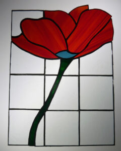
Like most tasks these days, I started with a Google search for “simple stained glass window.” The search brought up of nice examples, but I wanted something simple for my first try. This simple flower stood out:
It is from a tutorial that shows how to make your own real stained glass.
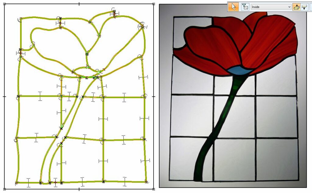
I took the image and imported it in to my CAD tool, SolidEdge, as a background in the drafting package. Then I used the sketcher to place splines on top of the image sort of representing the shape. If I had an artistic bone in my body, I probably could have started with a blank page and done something, but my lack of talent is well documented and I opted for tracing. It worked in 3rd grade, and it still works today. The resulting sketch looked like this, shown next to the original image:
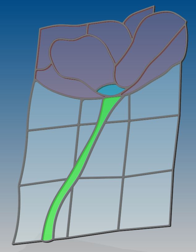
It is kind of hard to see in the image, but the “lead” in the image consists of boundaries, not a single line, forming a continuous area for all of the “lead” geometry. Each empty areas in the sketch was extruded up in the solid modeler to form the glass pieces. Here is what the solid looked like when I was done:
I assigned transparent colors in the CAD system to visualize it, show my preferred colors to the person setting up the 3D print, and because I figured it would look cool when I rendered it. Which it did:
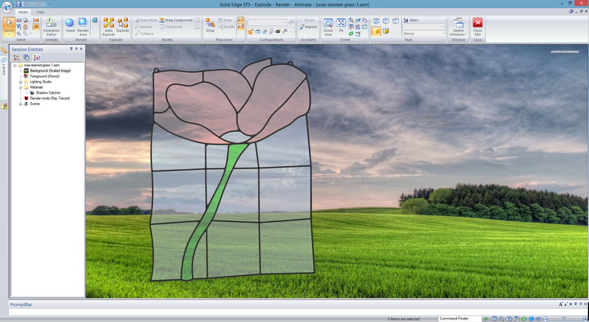
The next step was to simply save the assembly as an STL file. Our prototyping department took that file, massaged it a bit, and assigned colors from the available pallet.
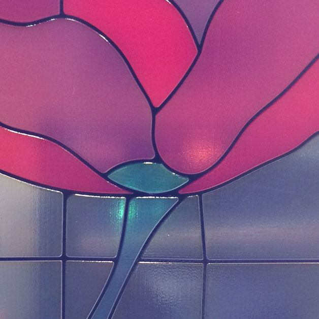
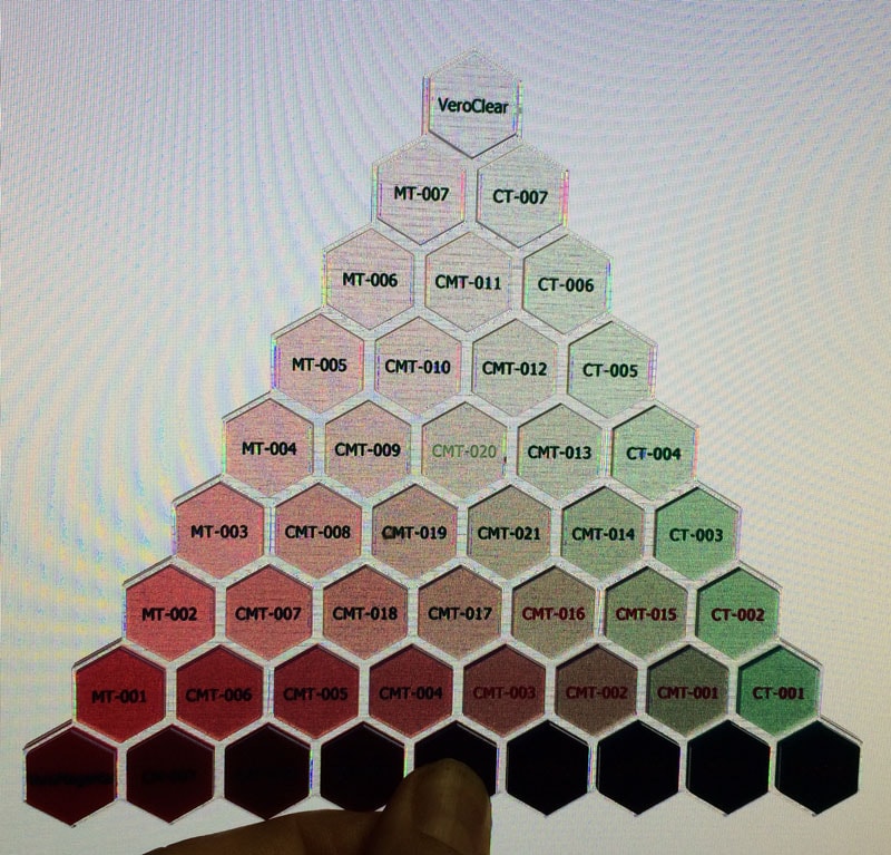
If you remember earlier articles on the Connex3, it uses four print heads: one for support material, and two for color, and one for a base material. In this case we used Veroclear as the base, magenta, and blue. Here is a 3D Print of the pallet we were working with (I used my computer monitor as a poor man’s light table, which looks bad on the picture but works well with your eyes):
The team assigned the colors we chose to the solids I created and next time the machine was not printing parts that actually generate income, the ran it.
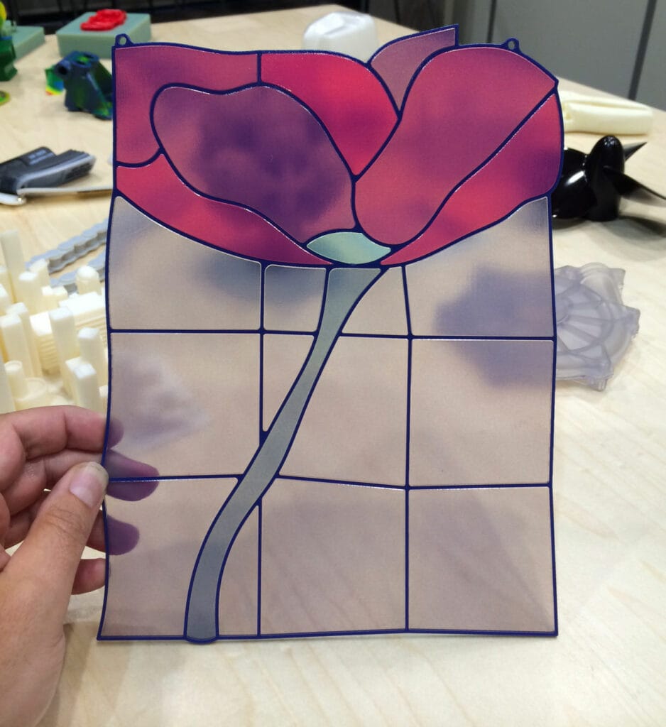
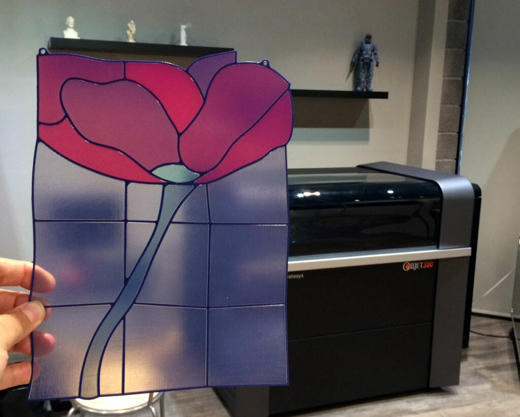
Here are some images of the results:
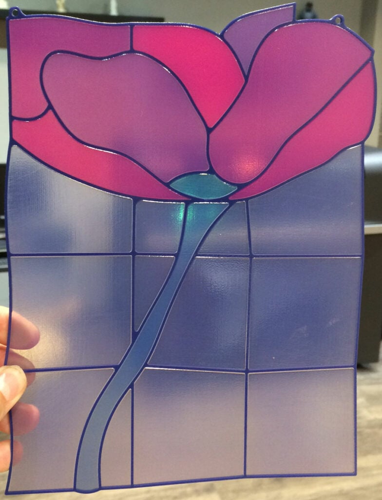
Here the final product is shown in front of the machine that it was made on:
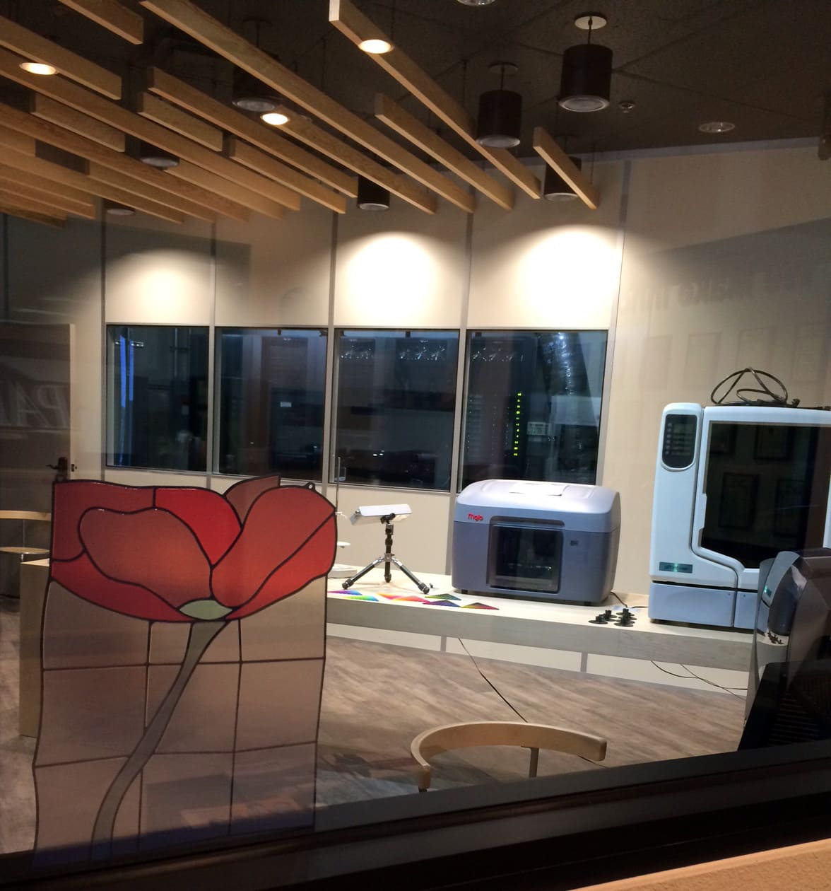
When I find some fishing line, I’ll hang it in front of the window, but here you can see it near where it will end up in front of the window to our Demo room.
Practical Applications
I have to say I’m pretty proud of my little side trip in to the artistic world, even if I did just trace someone’s design. And I am a big backer of Art for Art’s sake. However, that does not change the fact that we are an engineering company and I did do this to learn more about the technology so that we could apply it for customers.
Many parts that our customers make involve injection molding of different colored plastics, including transparent materials. This project illustrated who easy it is to replicate those components for prototyping, as an assembly. In addition to the clear material, we can run white, black, or even a soft rubber like material to replicate overmolding.
The simple 3D printed stained glass window shows the power of Stratasys’ PolyJet technology for creating robust and accurate prototypes of a huge range of parts, reducing development time, and giving engineers and creatives both a better tool to produce a better final product.
If you would like to learn more about this technology or to have PADT print parts for you, please feel free to contact us today.

