Recently we have had a few questions on obtaining contact results in ANSYS Mechanical. A lot of contact results can be accessed using the Contact Tool, but to obtain contact forces we use Probes. Since not everyone is familiar with how it’s done, we’ll explain the basics here.
Below is a screen shot of a Mechanical model involving two parts. One part has a load that causes it to be deflected into the other part.

We are interested in obtaining the total force that is being transmitted across the contact elements as the analysis progresses. Fortunately this is easy to do using Probes in Mechanical.
The first thing we do is click on the Solution branch in the tree so we can see the Probes button in the context toolbar. We then click on the Probe drop down button and select Force Reaction, as shown here:
Next, we click on the resulting Force Reaction result item under the Solution branch to continue with the configuration. We first change the Location Method from Boundary Condition to Contact Region:
We then specify the desired contact region for the force calculation from the Contact Region dropdown:
Note that the coordinate system for force calculation can either be Cartesian or Cylindrical. You can setup a coordinate system wherever you need it, selectable via the Orientation dropdown.
There is also an Extraction dropdown with various options for using the contact elements themselves, the elements underlying the contact elements, or the elements underlying the target elements (target elements themselves have no reaction forces or other results calculated). Care must be taken when using underlying elements to make sure we’re not also calculating forces from other contact regions that are part of the same elements, or from applied loads or constraints. In most cases you will want to use either Contact (Underlying Element) or Target (Underlying Element). If contact is non-symmetric, only one of these will have non zero values.
In this case, the setting Contact (Contact Element) was a choice that gave us appropriate results, based on our contact behavior method of Asymmetric:

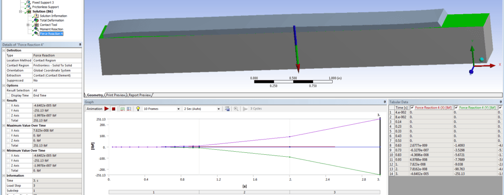
Here are the details including the contact force results:
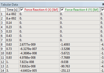
This is a close up of the force vs. ‘time’ graphs and table (this was a static structural analysis with a varying pressure load):
***** SUMMATION OF TOTAL FORCES AND MOMENTS IN THE GLOBAL COORDINATE SYSTEM *****
FX = -0.4640219E-04
FY = -251.1265
FZ = -0.1995618E-06
MX = 62.78195
MY = -0.1096794E-04
MZ = -688.9742
SUMMATION POINT= 0.0000 0.0000 0.0000
We hope this information is useful to you in being able to quickly and easily obtain your contact forces.


