In deciding to write this piece, I decided an interesting example would be the brace that is part of all curved saxophones. This brace connects the bell to the rest of the saxophone body, and provides stiffness and strength to the instrument. Various designs of this brace have been used by different manufacturers over the years. Since saxophone manufacturers like those in other industries are often looking for product differentiation, the use of an optimized organic shape in this structural component could be a nice marketing advantage.
This article is not intended to be a technical discourse on the principles behind topological optimization, nor is it intended to show expertise in saxophone design. Rather, the intent is to show an example of the kind of work that can be done using topological optimization and will hopefully get the creative juices flowing for lots of ANSYS users who now have access to this capability.
That being said, here are some images of example bell to body braces in vintage and modern saxophones. Like anything collectible, saxophones have fans of various manufacturers over the years, and horns going back to production as early as the 1920’s are still being used by some players. The older designs tend to have a simple thin brace connecting two pads soldered to the bell and body on each end. Newer designs can include rings with pivot connections between the brace and soldered pads.
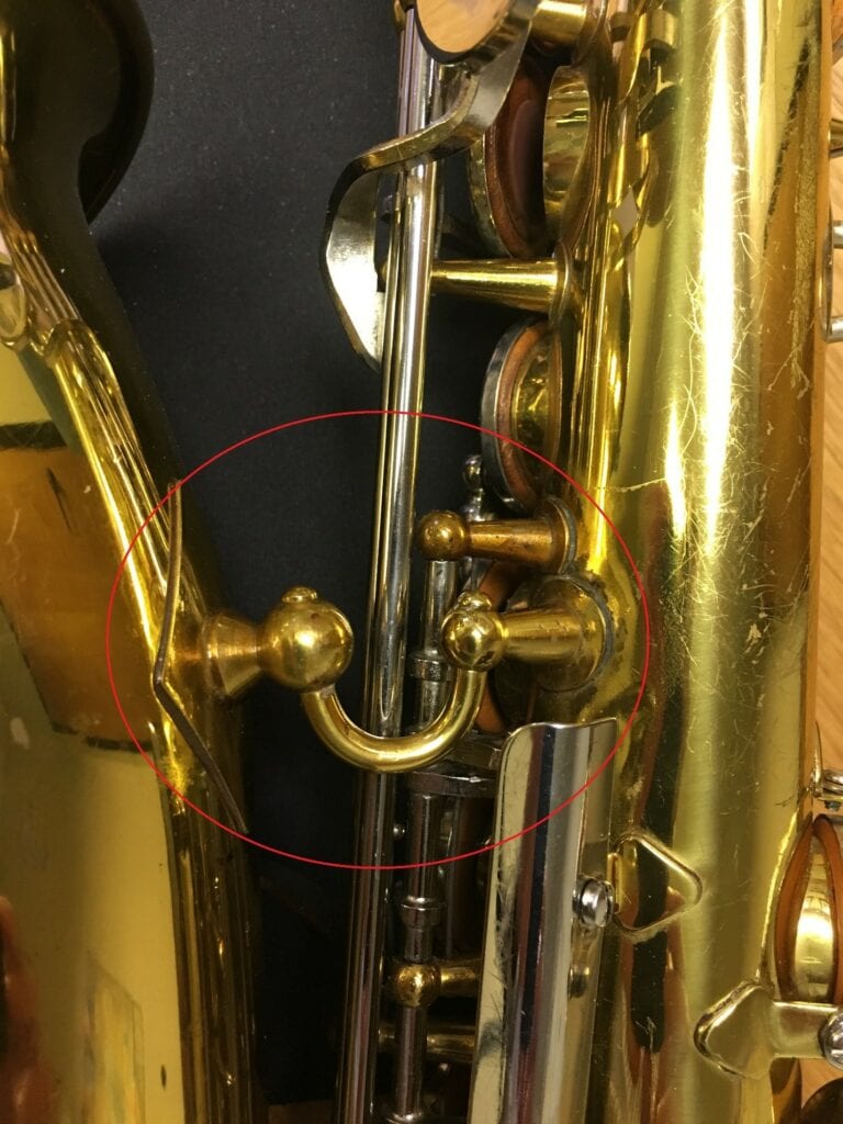
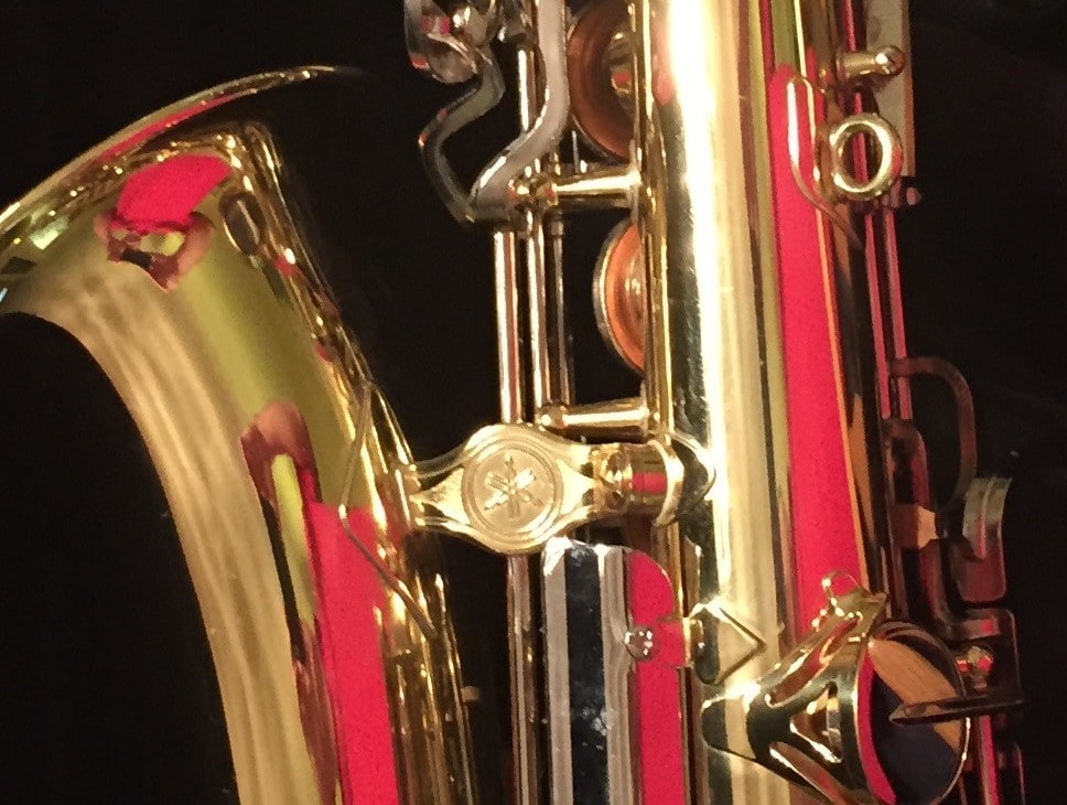
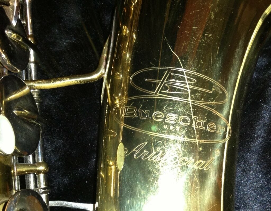
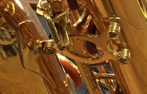
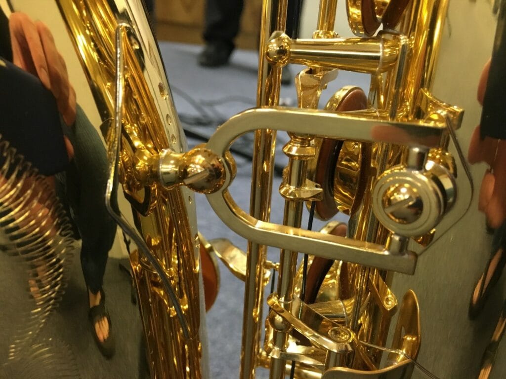
Hopefully those examples show there can be variation in the design of this brace, while not largely tampering with the musical performance of the saxophone in general. The intent was to pick a saxophone part that could undergo topological optimization which would not significantly alter the musical characteristics of the instrument.
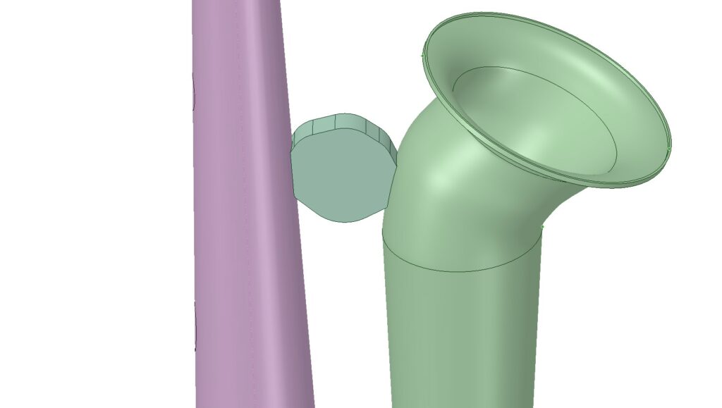
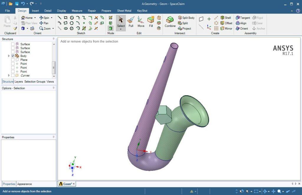
The first step was to obtain a CAD model of a saxophone body. Since I was not able to easily find one freely available on the internet that looked accurate enough to be useful, I created my own in ANSYS SpaceClaim using some basic measurements of an example instrument. I then modeled a ‘blob’ of material at the brace location. The idea is that the topological optimization process will remove non-needed material from this blob, leaving an optimized shape after a certain level of volume reduction.
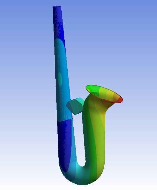
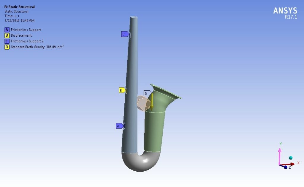
In ANSYS Mechanical, the applied boundary conditions consisted of frictionless support constraints at the thumb rest locations and a vertical displacement constraint at the attachment point for the neck strap. Acceleration due to gravity was applied as well. Other loads, such as sideways inertial acceleration, could have been considered as well but were ignored for the sake of simplicity for this article. The material property used was brass, with values taken from Shigley and Mitchell’s Mechanical Engineering Design text, 1983 edition.
This plot shows the resulting displacement distribution due to the gravity load:
Now that things are looking as I expect, the next step is performing the topological optimization.
Once the topological optimization ACT Extension has been downloaded from the ANSYS Customer Portal and installed, ANSYS Mechanical will automatically include a Topological Optimization menu:
I set the Design Region to be the blog of material that I want to end up as the optimized brace. I did a few trials with varying mesh refinement. Obviously, the finer the mesh, the smoother the surface of the optimized shape as elements that are determined to be unnecessary are removed from consideration. The optimization Objective was set to minimize compliance (maximize stiffness). The optimization Constraint was set to volume at 30%, meaning reduce the volume to 30% of the current value of the ‘blob’.
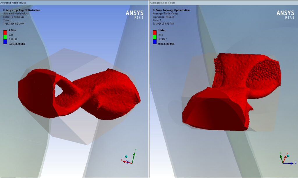
After running the solution and plotting Averaged Node Values, we can see the ANSYS-determined optimized shape:
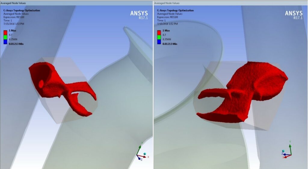
What is apparent when looking at these shapes is that the ‘solder patch’ where the brace attaches to the bell on one end and the body on the other end was allowed to be reduced. For example, in the left image we can see that a hole has been ‘drilled’ through the patch that would connect the brace to the body. On the other end, the patch has been split through the middle, making it look something like an alligator clip.
Another optimization run was performed in which the solder pads were held as surfaces that were not to be changed by the optimization. The resulting optimized shape is shown here:
Noticing that my optimized shape seemed on the thick side when compared to production braces, I then changed the ‘blob’ in ANSYS SpaceClaim so that it was thinner to start with. With ANSYS it’s very easy to propagate geometry changes as all of the simulation and topological optimizations settings stay tied to the geometry as long as the topology of those items stays the same.
Here is the thinner chunk after making a simple change in ANSYS SpacClaim:
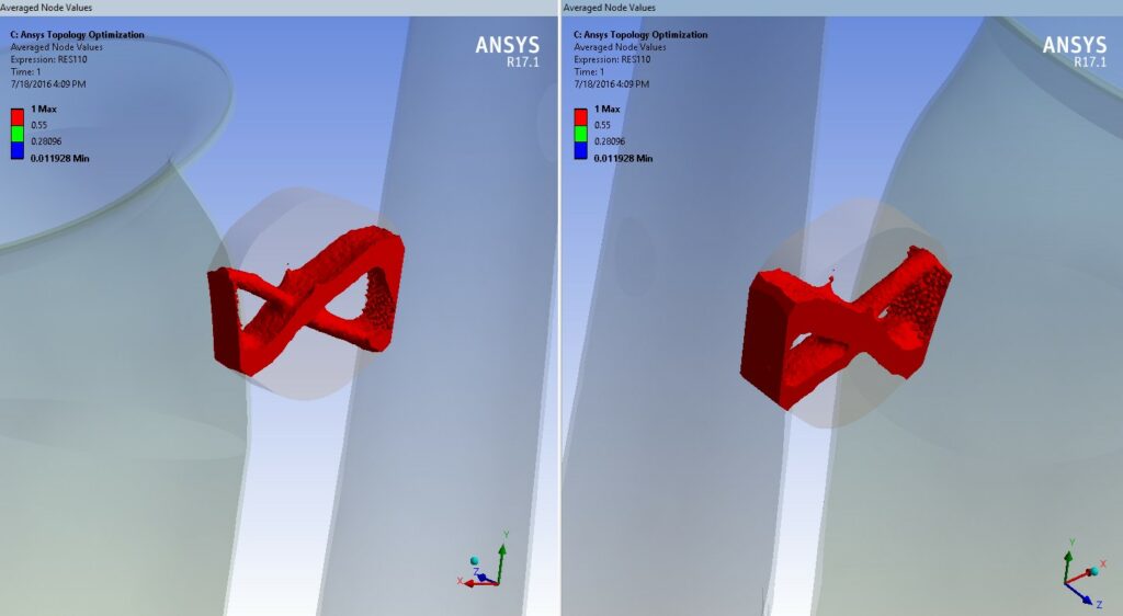
And here is the result of the topological optimization using the thinner blob as the starting point:
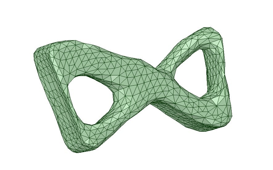
Using the ANSYS SpaceClaim Direct Modeler, the faceted STL file that results from the ANSYS topological optimization can be converted into a geometry file. This can be done in a variety of ways, including a ‘shrink wrap’ onto the faceted geometry as well as surfaces fit onto the facets. Another option is to fit geometry in a more general way in an around the faceted result. These methods can also be combined. SpaceClaim is really a great tool for this. Using SpaceClaim and the topological optimization (faceted) result, I came up with three different ‘looks’ of the optimized part.
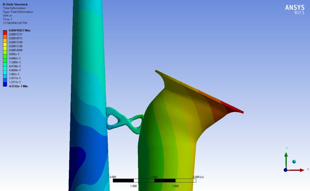
Using ANSYS Workbench, it’s very easy to plug the new geometry component into the simulation model that I already had setup and run in ANSYS Mechanical using the ‘blob’ as the brace in the original model. I then checked the displacement and stress results to see how they compared.
First, we have an organic looking shape that is mostly faithful to the results from the topological optimization run. This image is from ANSYS SpaceClaim, after a few minutes of ‘digital filing and sanding’ work on the STL faceted geometry output from ANSYS Mechanical.
This shows the resulting deflection from this first, ‘organic’ candidate:
The next candidate is one where more traditional looking solid geometry was created in SpaceClaim, using the topological optimization result as a guide. This is what it looks like:
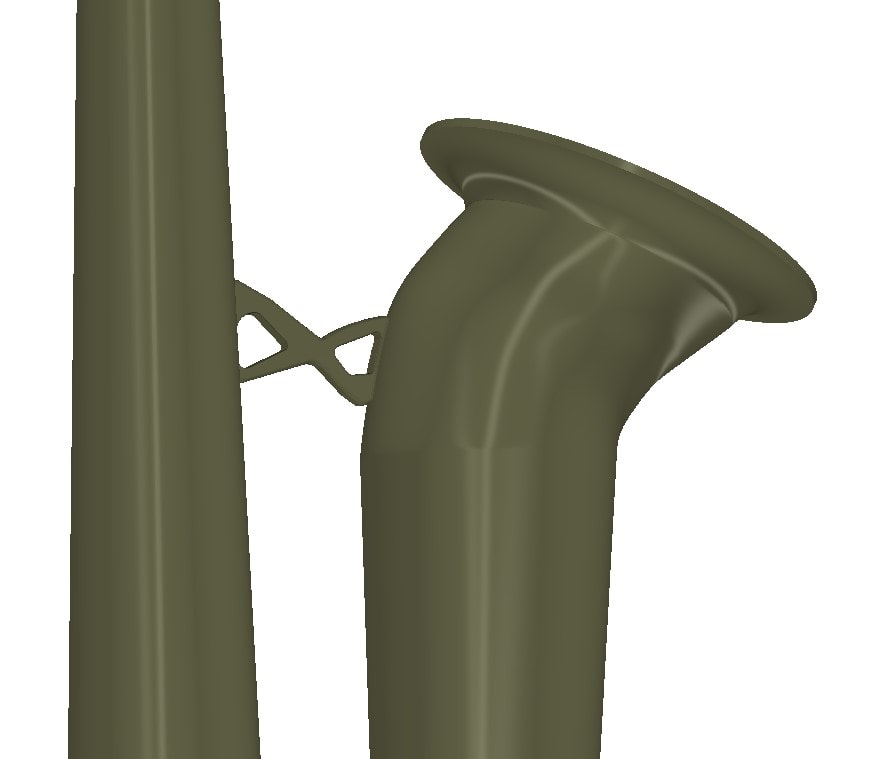
This is the same configuration, but showing it in place within the saxophone bell and body model in ANSYS SpaceClaim:
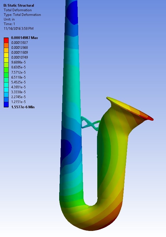
Next, here is the deformation result for our simple loading condition using this second geometry configuration:
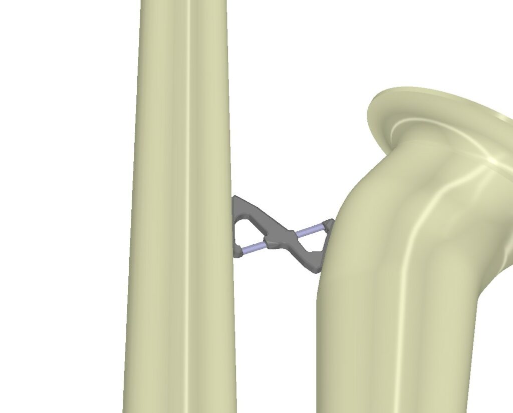
The third and final design candidate uses the second set of geometry as a starting point, and then adds a bit of style while still maintaining the topological optimization shape as an overall guide. Here is this third candidate in ANSYS SpaceClaim:
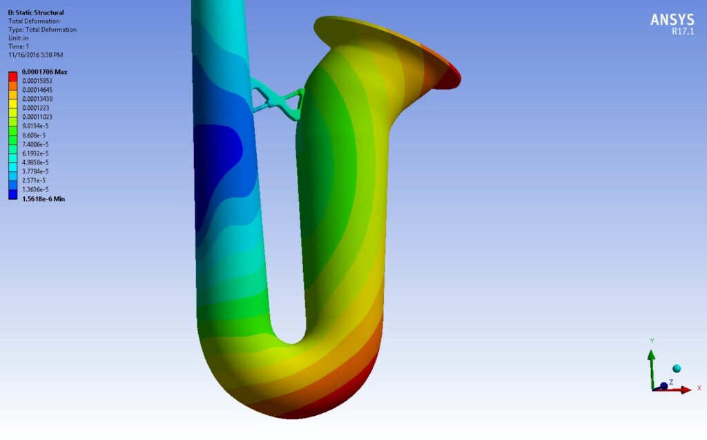
Here are is the resulting displacement distribution using this design:
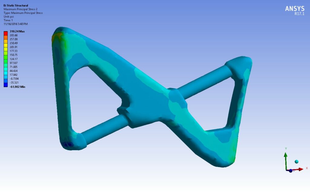
This shows the maximum principal stress distribution within the brace for this candidate:
Again, I want to emphasize that this was a simple example and there are other considerations that could have been included, such as loading conditions other than acceleration due to gravity. Also, while it’s simple to include modal analysis results, in the interest of brevity I have not included them here. The main point is that topological optimization is a tool available within ANSYS Mechanical using the ACT extension that’s available for download on the customer portal. This is yet another tool available to us within our ANSYS simulation suite. It is my hope that you will also explore what can be done with this tool.
Regarding this effort, clearly a next step would be to 3D print one or more of these designs and test it out for real. Time permitting, we’ll give that a try at some point in the future.

