You kids don’t know how good you have it with automatic contact creation in Mechanical. Back in my day, I’d have to use the contact wizard in MAPDL or show off my mastery of the ESURF command to define contacts between parts. Sure, there were some macros somewhere on the interwebs that would go through and loop for surfaces within a particular offset, but for the sake of this stereotypical “old-tyme” rant, I didn’t use them (I actually didn’t, I was just TOO good at using ESURF to need anyone else’s help).

Hey, it gets me from point A to B
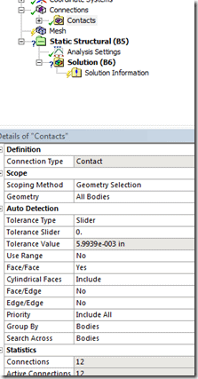
In Mechanical contact is automatically generated based on a set of rules contained in the ‘Connection Group’ object:
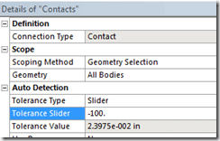
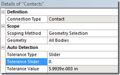
It might look a little over-whelming, but really the only thing you’ll need to play around with is the ‘Tolerance Type’. This can either ‘Slider’ or ‘Value’ (or use sheet thickness if you’re working with shells). What this controls is the face offset value for which Mechanical will automatically build contact. So in the picture shown above faces that are 5.9939E-3in apart will automatically have contact created. You can play around with the slider value to change what the tolerance
 |
 |
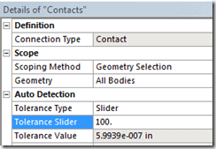 |
As you can see, the smaller the tolerance slider the larger the ‘acceptable’ gap becomes. If you change the Tolerance Type to be ‘Value’ then you can just directly type in a number.
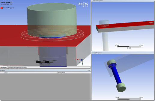
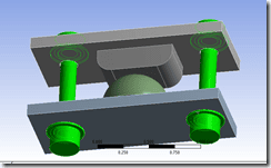
Typically the default values do a pretty good job automatically defining contact. However, what happens if you have a large assembly with a lot of thin parts? Then what you run into is non-sensical contact between parts that don’t actually touch (full disclosure, I actually had to modify the contact settings to have the auto-generated contact do something like this…but I have seen this in other assemblies with very thin/slender parts stacked on top of each other):
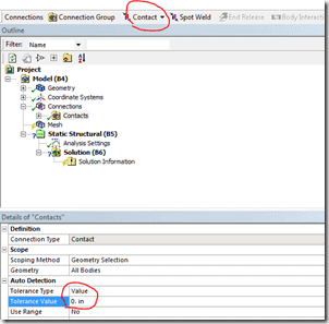
In the image above, we see that contact has been defined between the bolt head and a plate when there is clearly a washer present. So we can fix this by going in and specifying a value of 0, meaning that only surfaces that are touching will have contact defined. But now let’s say that some parts of your assembly aren’t touching (maybe it’s bad CAD, maybe it’s a welded assembly, maybe you suppressed parts that weren’t important).
The brute force way to handle this would be to set the auto-detection value to be 0 and then go back and manually define the missing contacts using the options shown in the image above. Or, what we could do is modify the auto-contact to be broken up into groups and apply appropriate rules as necessary. The other benefit to this is if you’re working in large assemblies, you can retain your sanity by having contact generated region by region. In the words of the original FE-guru, Honest Abe, it’s easier to manage things when they’re logically broken up into chunks.
Said No One Ever
Sorry…that was bad. I figured in the new alt-fact world with falsely-attributed quotes to historical leaders, I might as well make something up for the oft-overlooked FE-crowd.
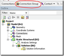
So, how do you go about implementing this? Easy, first just delete the default connection group (right-mouse-click on it and select delete). Next, just select a group of bodies and click the ‘Connection Group’ button:
 |
 |
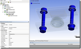 |
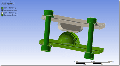
In the image series above, I selected all the bolts and washers, clicked the connection group, and now I have created a connection group that will only automatically generate contact between the bolts and washers. I don’t have to worry about contact being generated between the bolt and plate. Rinse, lather, and repeat the process until you’ve created all the groups you want:
ALL the Connection Groups!
Now that you have all these connection groups, you can fine-tune the auto-detection rules to meet the ‘needs’ of those individual body groups. Just zooming in on one of the groups:
By default, when I generate contact for this group I’ll get two contact pairs:
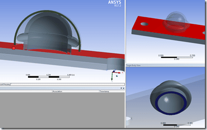 |
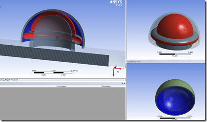 |
While this may work, let’s say I don’t want a single contact pair for the two dome-like structures, but 2. That way I can just change the behavior on the outer ‘ring’ to be frictionless and force the top to be bonded:
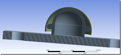
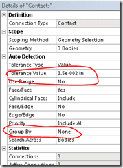
I modified the auto-detection tolerance to be a user-defined distance (note that when you type in a number and move your mouse over into the graphics window you will see a bulls-eye that indicates the search radius you just defined). Next, I told the auto-detection not to group any auto-detected contacts together. The result is I now get 3 contact pairs defined:
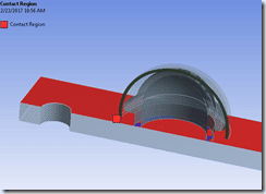 |
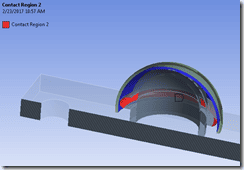 |
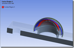 |
Now I can just modify the auto-generated contacts to have the middle-picture shown in the series above to be frictionless. I could certainly just manually define the contact regions, but if you have an assembly of dozens/hundreds of parts it’s significantly easier to have Mechanical build up all the contact regions and then you just have to modify individual contact pairs to have the type/behavior/etc you want (bonded, frictionless, symmetric, asymmetric, custom pinball radius, etc). This is also useful if you have bodies that need to be connected via face-to-edge or edge-to-edge contact (then you can set the appropriate priority as to which, if any of those types should be preserved over others).
So the plus side to doing all of this is that after any kind of geometry update you shouldn’t have much, if any, contact ‘repair’ to do. All the bodies/rules have already been fine tuned to automatically build what you want/need. You also know where to look to modify contacts (although using the ‘go to’ functionality makes that pretty easy as well). That way you can define all these connection groups, leave everything as bonded and do a preliminary solve to ensure things look ‘okay’. Then go back and start introducing some more reality into the simulation by allowing certain regions to move relative to each other.
The downside to doing your contacts this way is you risk missing an interface because you’re now defining the load path. To deal with that you can just insert a dummy-modal environment into your project, solve, and check that you don’t have any 0-Hz modes.

