In my previous article, I wrote about how you get what you pay for with your analysis package. Well, buckle up for some more…but this time we’ll just focus on handling assemblies in your structural/thermal simulations. If all you’re working on are single components, count yourself lucky. Almost every simulation deals with one part interacting with another. You can simplify your boundary conditions a bit to make it equivalent, but if you have significant bearing stresses, misalignments, etc…you need to include the supporting parts. Better hope your analysis package can handle contact…

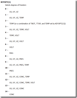
First off, contact isn’t just for structural simulations. Contact allows you to pass loads across difference meshes, meaning you don’t need to create a conformal mesh between two parts in order to simulate something. Here’s a quick listing on the degrees of freedom supported in ANSYS (don’t worry…you don’t need to know how to set these options as ANSYS does it for you when you’re in Workbench):
You can use contact for structural, thermal, electrical, porous domain, diffusion, or any combination of those. The rest of this article is going to focus on the structural side of things, but realize that the same concepts apply to essentially any analysis you can do within ANSYS Mechanical..
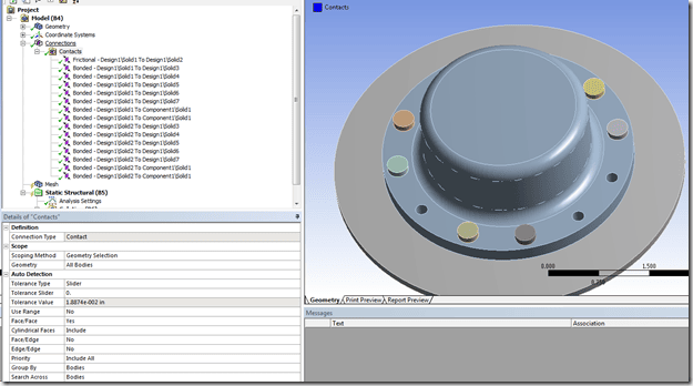
First, it’s incredibly easy to create contact in your assembly. Mechanical automatically looks for surfaces within a certain distance from one another and builds contact. You can further customize the automated process by defining your own connection groups, as I previous wrote about. These connection groups can create contact between faces, edges, solids bodies, shell bodies, and line bodies.
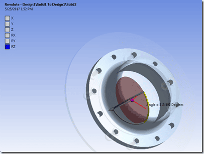
Second, not only can you create contact to transfer loads across different parts, but you can also automatically create joints to simulate linkages or ‘linearize’ complicated contacts (e.g. cylindrical-to-cylindrical contact for pin joints). With these joints you can also specify stops and locks to simulate other components not explicitly modeled. If you want to really model a threaded connection you can specify the pitch diameter and actually ‘turn’ your screw to properly develop the shear stress under the bolt head for a bolted joint simulation without actually needing to model the physical threads (this can also be done using contact geometry corrections)
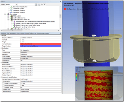
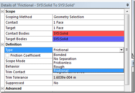
If you’re *just* defining contact between two surfaces, there’s a lot you simulate. The default behavior is to bond the surfaces together, essentially weld them closed to transmit tensile and compressive loads. You also have the ability to let the surfaces move relative to each other by defining frictionless, frictional, rough (infinite coefficient of friction), or no-separation (surfaces don’t transmit shear load but will not separate).
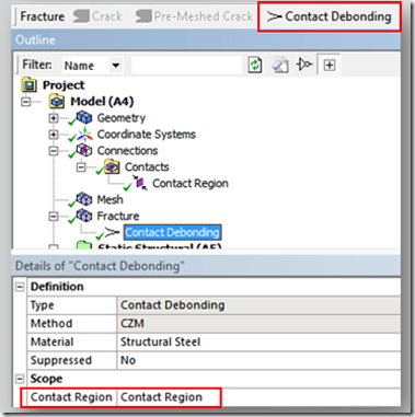
Some other ‘fancy’ things you can do with contact is simulate delamination by specifying adhesive properties (type I, II, or III modes of failure). You can add a wear model to capture surface degradation due to normal stress and tangential velocity of your moving surfaces. You can simulate a critical bonding temperature by specifying at what temperature your contacts ‘stick’ together instead of slide. You can specify a ‘wetted’ contact region and see if the applied fluid pressure (not actually solving a CFD simulation, just applying a pressure to open areas of the contact interface) causes your seal to open up.
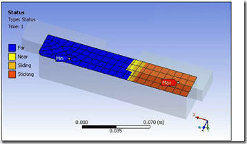
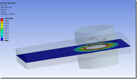
Now, it’s one thing to be able to simulate all of these behaviors. The reason you’re running a finite element simulation is you need to make some kind of engineering judgement. You need to know how the force/heat/etc transfers through your assembly. Within Mechanical you can easily look at the force for each contact pair by dragging/dropping the connection object (contact or joint) into the solution. This will automatically create a reaction probe to tell you the forces/moments going through that interface. You can create detailed contour plots of the contact status, pressure, sliding distance, gap, or penetration (depending on formulation used).
Again, you can generate all of that information for contact between surface-to-surface, surface-to-edge, or edge-to-edge. This allows you to use solids, shells, beams, or any combination you want, for any physics you want, to simulate essentially any real-world application. No need to buy additional modules, pay for special solvers, fight through meshing issues by trying to ‘fake’ an assembly through a conformal mesh. Just import the geometry, simplify as necessary (SpaceClaim is pretty awesome if you haven’t heard), and simulate it.)
For a more detailed, step-by-step look at the process, check out the following video!

