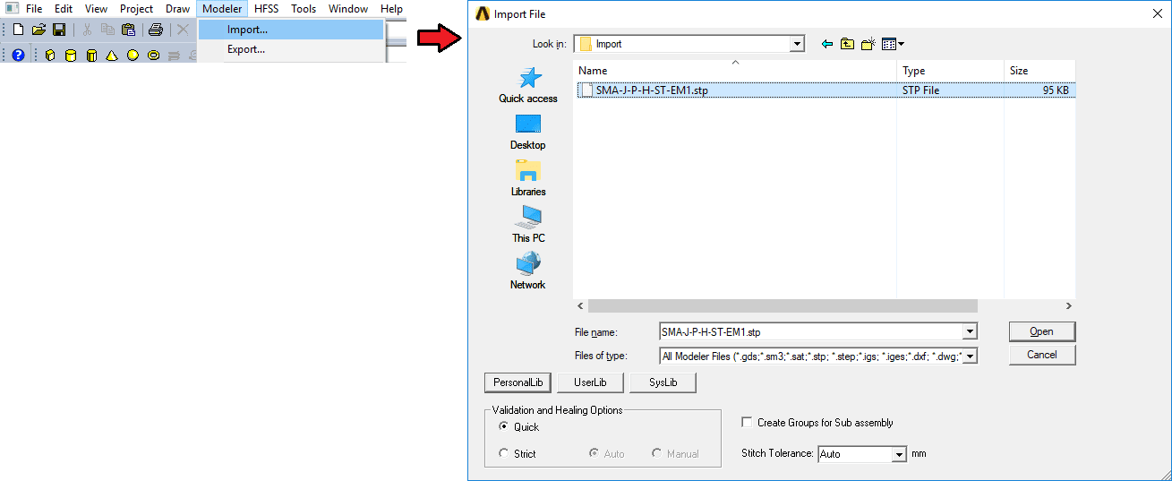
Importing solid 3D Mechanical CAD (or MCAD) models into ANSYS HFSS has always been and remains to be a fairly simple process. After opening ANSYS Electronics Desktop and creating an HFSS design, from the menu bar, select Modeler > Import. A dialog box will open to navigate to and directly open the model.
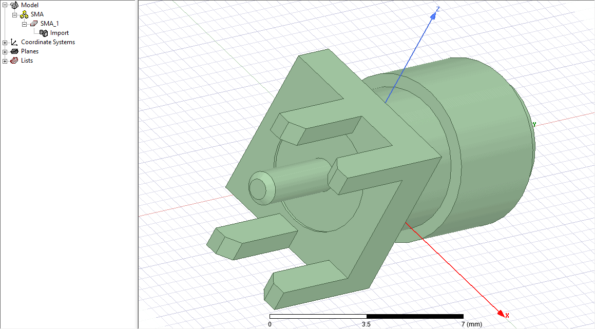
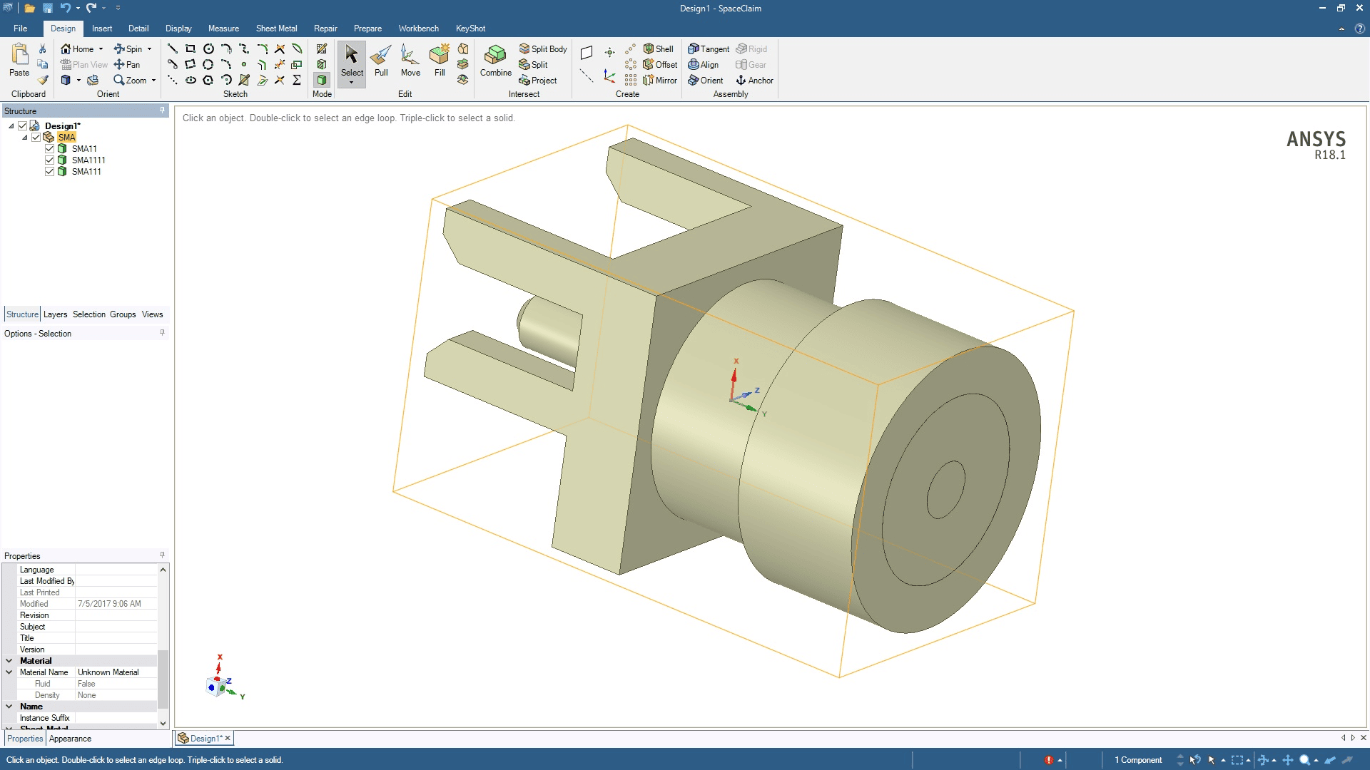
The CAD will automatically be translated and loaded into the HFSS 3D Modeler. If the geometry is correct and does not require any editing, the import process is complete and analysis can begin! However, if there are any errors with the geometry, there is excessive or invalid detail, or if it’s not organized into separate bodies conducive for electromagnetic analysis, you may soon realize that the editing capability is limited to scaling, reorienting, or Boolean operations. This approach can be particularly troublesome when portions of the model (or all of the model) which consist of different materials are not split into different objects. For example, notice the outer conductor, inner conductor, and dielectric of the imported SMA below are all one solid object.
Unless you’re lucky enough to work with the creator of the CAD, you will need to find a way to split this model into the inner and outer conductors, and the dielectric. However, since the release of ANSYS R18.1, the power of SpaceClaim Direct Modeler (SCDM) and the MCAD translator will be packaged together. The good news is, the process described above will continue to work. The better news is, SCDM offers new capabilities to directly edit or clean imported geometry. So, here are a few simple steps to quickly split this SMA connector using SCDM. You can download a copy of this model here to follow along. If you need access to SCDM, you can contact us at info@padtinc.com. It’s worth noting, at this point, that the processes discussed throughout this article work the same for HFSS-IE, Q3D, and Maxwell designs as well.
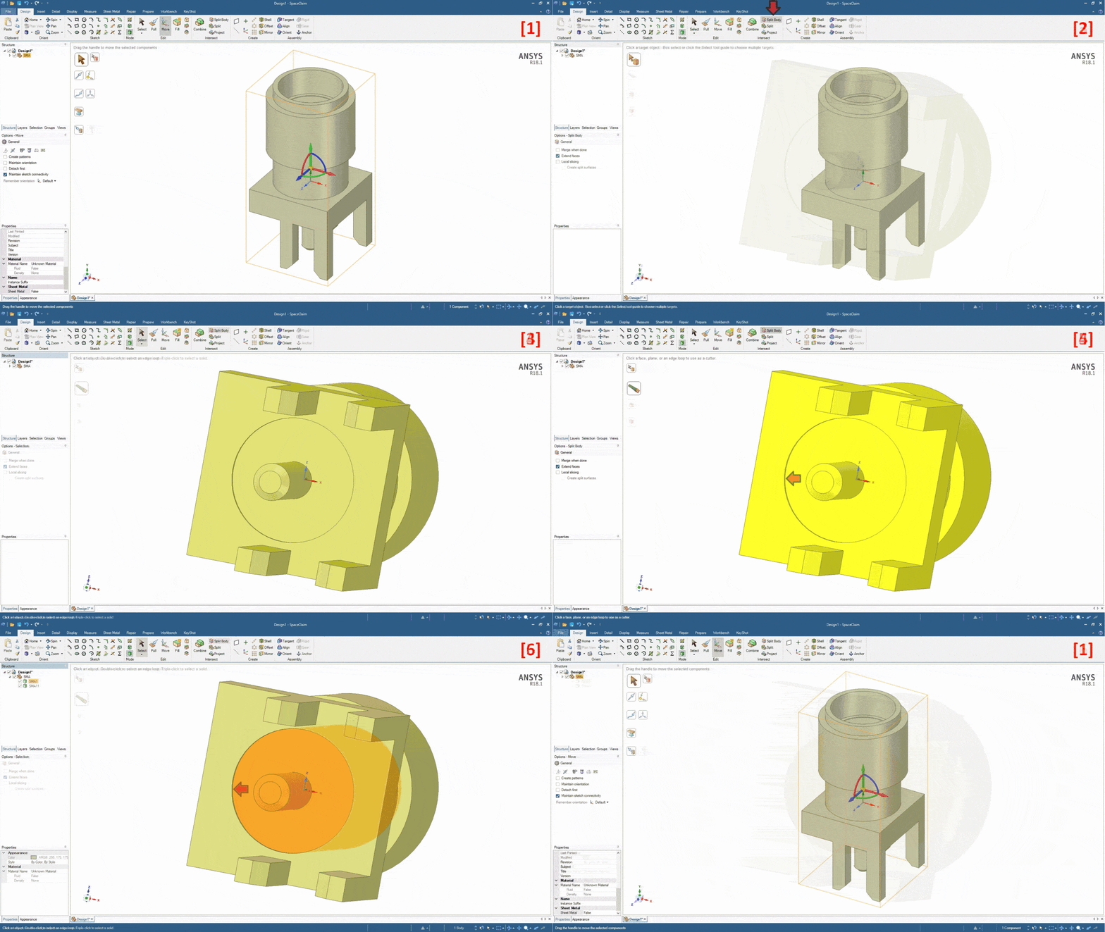
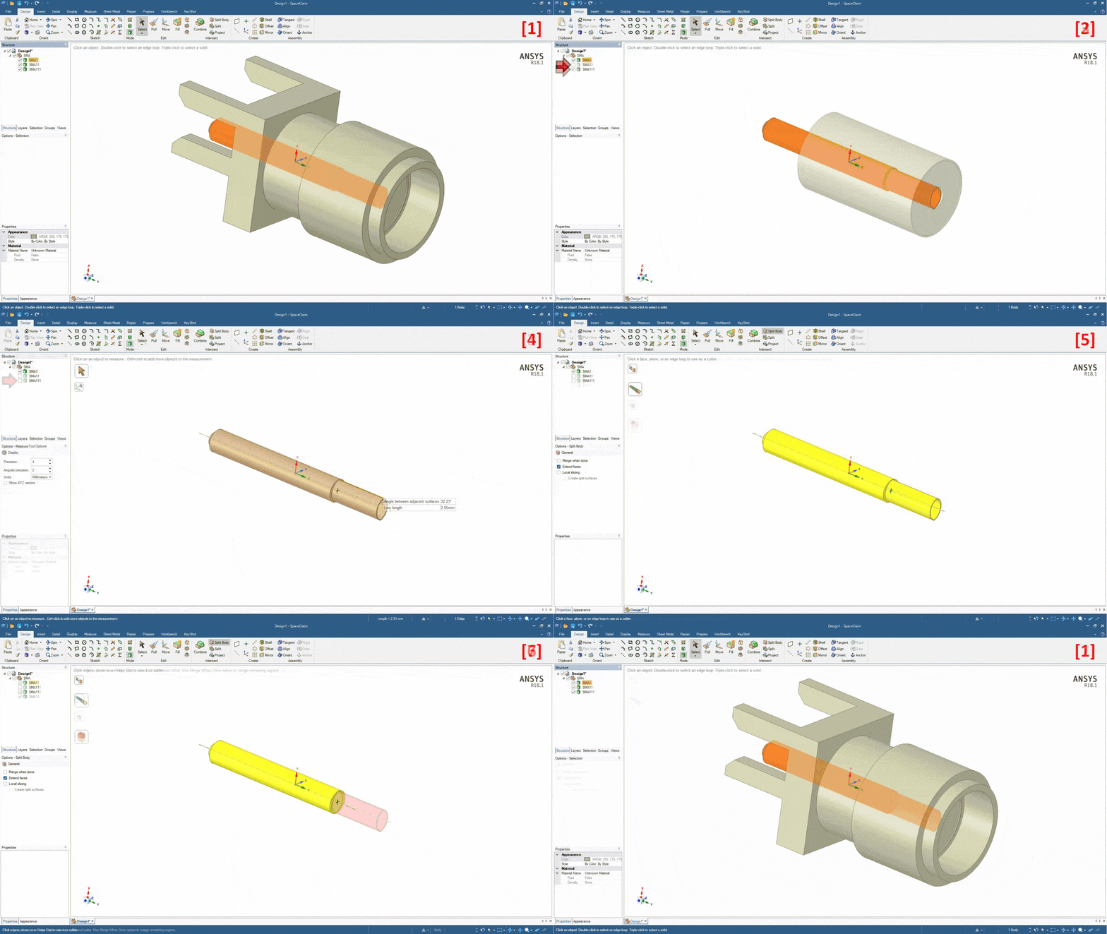
[1] First, after opening ANSYS SpaceClaim, the step file can be imported through the menu File > Open or by simply dragging and dropping the file into the SCDM window. [2] To separate the dielectric from the outer conductor, select Design > Intersect > Split Body. [3] Click and hold the center mouse button to rotate the model so the boundary between the dielectric and outer conductor is visible. Hold the Ctrl key and click the center mouse button to pan, and use the center mouse scroll to zoom in and out. Finally, press ‘z’ on the keyboard to fit the view window. [4] When positioned, click on the object to split (in this case it is the entire model). [5] Then, click on the face which defines the boundary between the dielectric and outer conductor. [6] Finally, press the Esc key. The first split is done!
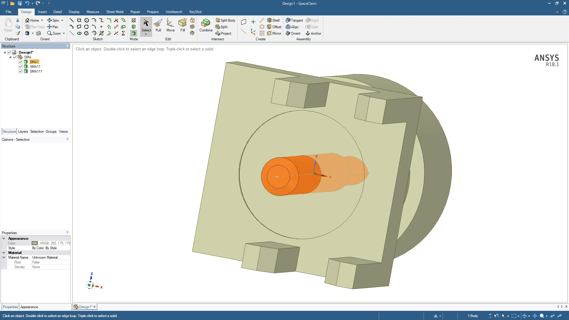
Repeat the Split Body process to separate the center conductor from the dielectric. Notice under the structure tree that there are now three separate objects.
The split body function is also useful to simplify a structure for analysis. For example, the female side of the SMA could be simplified as a solid center conductor. [1] Reposition the connector to view the female side. [2]-[3] Control the visibility of each body with the object’s checkbox in the structure tree. [4] Measure the length of the female side by pressing the letter ‘e’ on the keyboard and selecting the top edge (note the line length of 2.95mm for later). [5] Then, repeat the Split Body process to split the center conductor at the boundary between the male and female sides. [6]-[7] However, rather than pressing the Esc key, click on the female receiver to automatically remove the body.
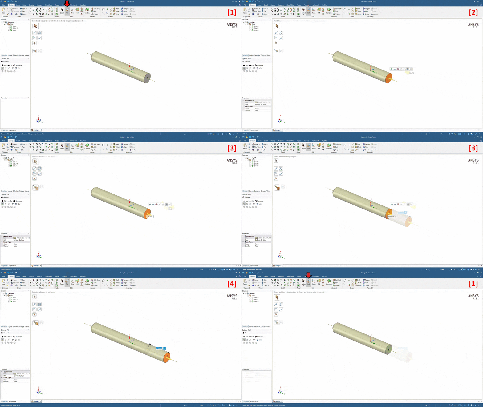
[1] To extend the center pin to its original length, select Design > Edit > Pull. [2] Click on the face where the female side was originally attached and select the Up To option. [3] Type in the previously measured length of 2.95mm. [4] Finally, press Enter (press Esc 3x to exit the Pull command).
Repeat the Split Body and Pull processes until the model has been divided into different bodies for each material type and is sufficiently simplified.
Once the model is ready, select File > Save As to save the geometry as the preferred format. Perhaps the most familiar approach to HFSS users would be to save the new model as a STEP file, then to import the model into HFSS as described in the first paragraph.

