One of the great new features in ANSYS Mechanical 19.2 is the ability to perform a lattice optimization. Accomplished as an option within Topology Optimization, lattice optimization allows us to generate a lattice structure within our region of interest. It includes varying thickness of the lattice members as part of the optimization.
Lattice structures can be very beneficial because weight can be substantially reduced compared to solid parts made using traditional manufacturing methods. Further, recent advances in additive manufacturing enable the creation of lattice structures in ways that weren’t possible with traditional manufacturing.
Here I’ll explain how to perform a lattice optimization in ANSYS 19.2 step by step.
The procedure starts the same as a normal topology optimization in ANSYS Mechanical, with an initial static structural analysis on our original part or assembly. If you’re not familiar with the process, this earlier PADT Focus blog should be helpful: https://www.padtinc.com/blog/the-focus/topological-optimization-in-ansys-18-1-motorcycle-component-example
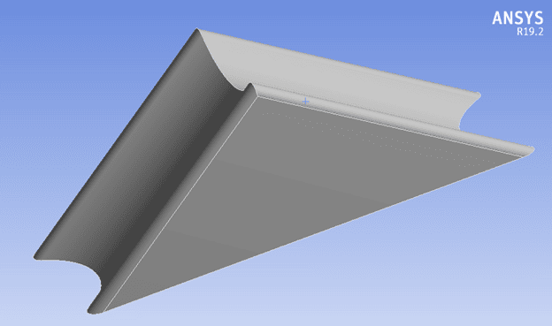
For the lattice optimization, I’m starting with a part I created that acts as a corner brace:
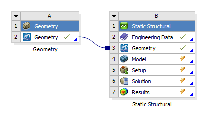
At this early point in the simulation, the Project Schematic looks like this:
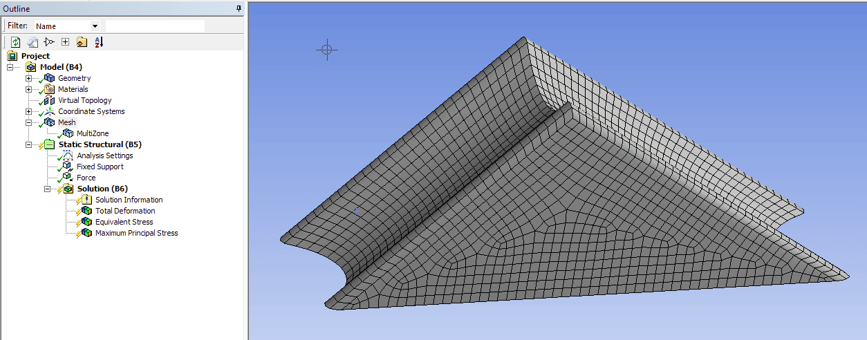
I used the Multizone mesh method to get a hex mesh on the part:
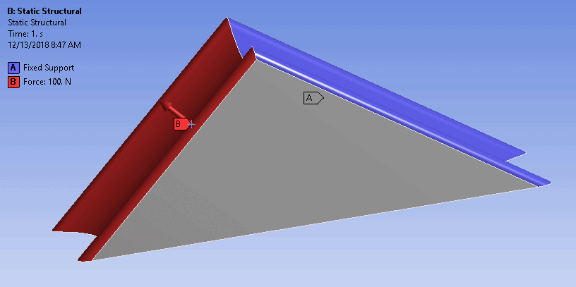
Simple loads and constraints are recommended especially if you’ll be doing a downstream validation study. That is because the downstream simulation on the resulting lattice geometry will most likely need to operate on the FE entities rather than geometric entities for load and constraint application. The boundary conditions in this simple model consisted of a fixed support on one side of the brace and a force load on the other side:
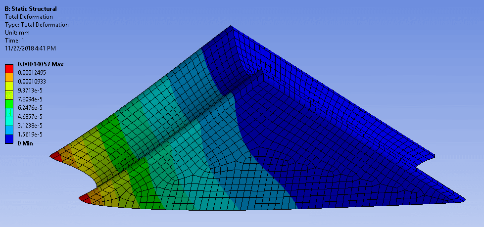
After solving, I reviewed the displacement as well as the stress results:
Satisfied with the results, the next step is to add a Topology Optimization block in the Project Schematic. The easiest way to do this is to right click on the Solution cell, then select Transfer Data to New > Topology Optimization:
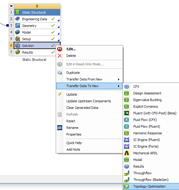
You may need to re-solve the static structural simulation at this point. You’ll know if you have yellow thunderbolts in the Project Schematic instead of green checkmarks for the Static Structural analysis.
At this point, the Project Schematic now looks like this:

The Mechanical window now has the Topology Optimization branch added:
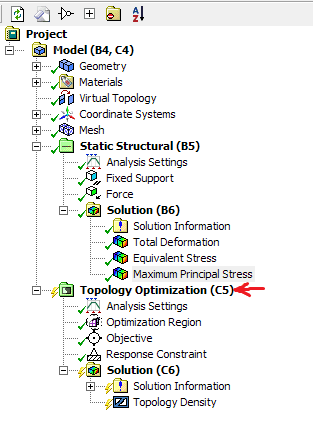
The change to make to enable a lattice optimization is accomplished in the details view of the Optimization Region branch:
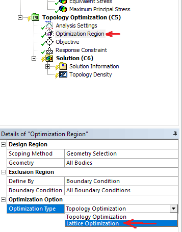
We then need to specify some settings for the lattice. The first of these is the Lattice Type. The various types are documented in the ANSYS 19.2 Help. In my example I selected the Crossed option.
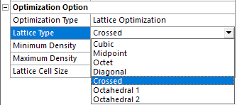
The other properties to define are:
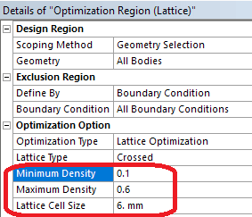
- Minimum Density (to avoid lattice structures that are toothin. Allowed bounds are 0 and 1)
- Maximum Density (elements are considered full/solid fordensities higher than this value, allowed bounds are 0 and 1)
- Lattice Cell Size (used in downstream geometry steps andadditive manufacturing)
Values I used in my example are shown here:
Assuming no other options need to be set, we solve the lattice optimization and review the results. The results are displayed as a contour plot with values between zero and one, with values corresponding to the density settings as specified above.
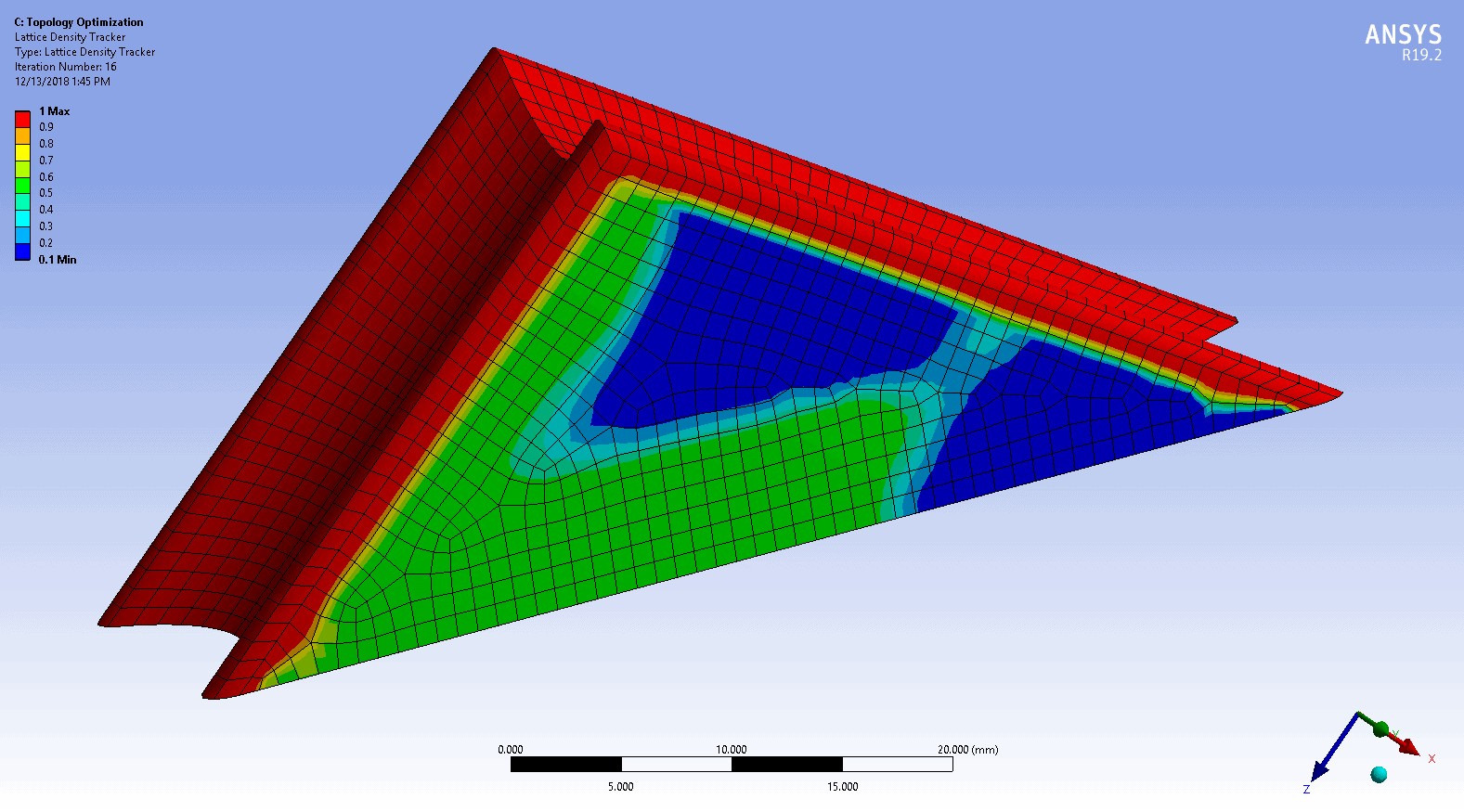
Note that at this stage we don’t actually visualize the lattice structure – just a contour plot of where the lattice can be in the structure. Where density values are higher than the maximum density specified, the geometry will end up being solid. The lattice structure can exist where the results are between the minimum and maximum density values specified, with a varying thickness of lattice members corresponding to higher and lower densities.
The next step is to bring the lattice density information into SpaceClaim and generate actual lattice geometry. This is done by adding a free standing Geometry block in the Workbench Project Schematic.

The next step is to drag and drop the Results cell from the Topology Optimization block onto the Geometry cell of the new free standing Geometry block:

The Project Schematic will now look like this:

Notice the Results cell in the Topology Optimization branch now has a yellow lightning bolt. The next step is to right click on that Results cell and Update. The Project Schematic will now look like this:

Before we can open SpaceClaim, we next need to right click on the Geometry cell in the downstream Geometry block and Update that as well:
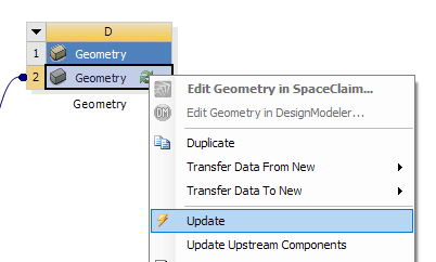
After both Updates, the Project Schematic will now look like this:

The next step is to double click or right click on the now-updated Geometry cell to open SpaceClaim. Note that both the original geometry and a faceted version of the geometry will exist in SpaceClaim:
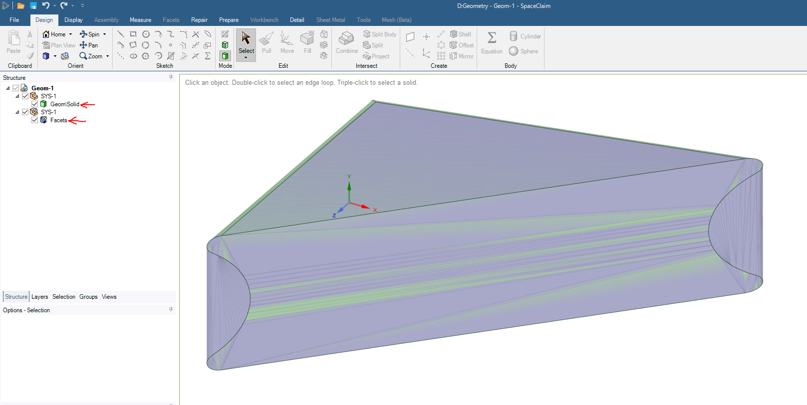
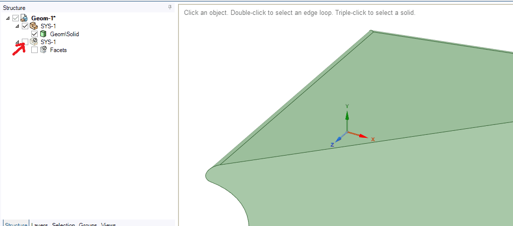
It may seem counter intuitive, but we actually suppress the faceted geometry and only work with the original, solid geometry for the faceted process. The faceted geometry should be automatically suppressed, as shown by the null symbol, ø, in the SpaceClaim tree. At this point it will be helpful to hide the faceted geometry by unchecking its box in the tree:
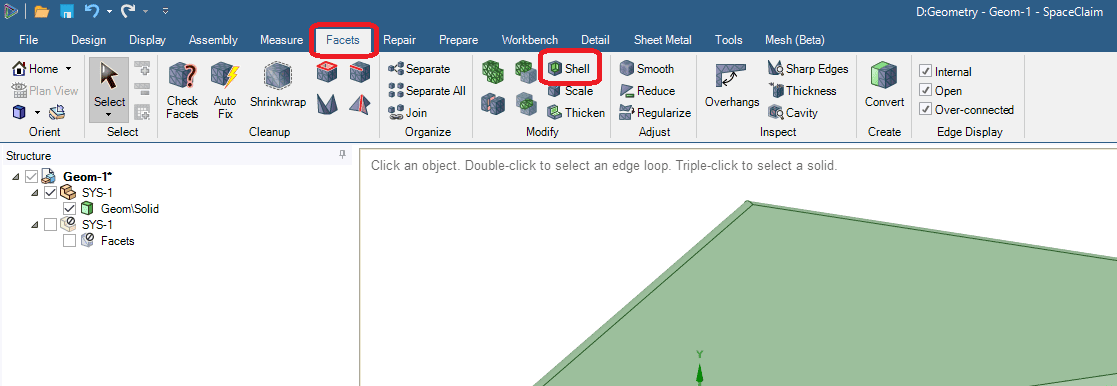
Next we’ll utilize some capability in the Facets menu in SpaceClaim to create the lattice geometry, using the lattice distribution calculated by the lattice optimization. Click on the Facets tab, then click on the Shell button:
Set the Infill option to be Basic:
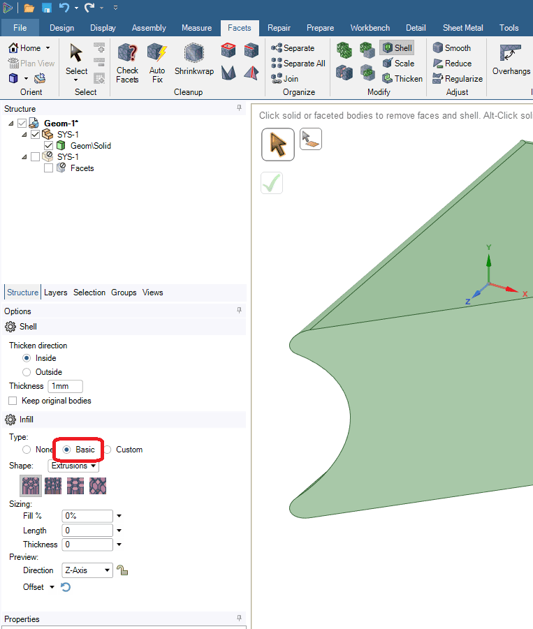
At this point there should be a check box for “Use Density Attributes” below the word Shape. This check box doesn’t always appear. If it’s not there, first try clicking on the actual geometry object in the tree:
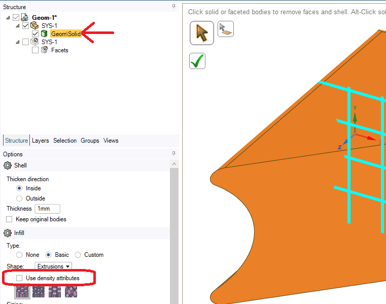
In one instance I had to go to %appdata%\Ansys and rename the v192 folder to v192.old to reset Workbench preferences and launch Workbench again. That may have been ‘pilot error’ on my part as I was learning the process.
The next step is to check the Use density attributes box. The Shape dropdown should be set to Lattices. Once the Use density attributes box is checked, we can then one of the predefined lattice shapes, which will be used for downstream simulation and 3D printing. The shape picked needs to match the lattice shape previously picked in the topology optimization.
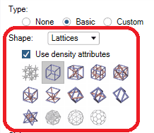
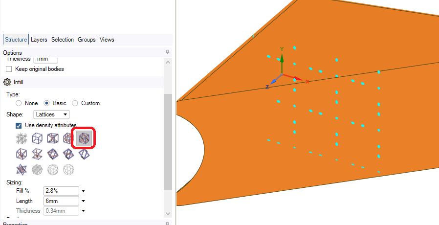
In my case I selected the Cube Lattice with Side Diagonal Supports, which corresponds to the Crossed selection I made in the upsteam lattice optimization. Note that a planar preview of this is displayed inside the geometry:
The next step is to click the green checkmark to have SpaceClaim create the lattice geometry based on the lattice distribution calculated by the lattice optimization:
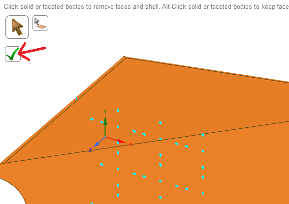
When SpaceClaim is done with the lattice geometry generation, you should be able to see a ghosted image showing the lattice structure in the part’s interior:
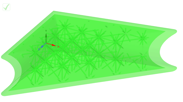
Note that if you change views, etc., in SpaceClaim, you may then see the exterior surfaces of the part, but rest assured the lattice structure remains in the interior.
Your next step may need to be a validation. To do this, we create a standalone Static Structural analysis block on the Project Schematic:

Next we drag and drop the Geometry cell from the faceted geometry block we just created onto the Geometry cell of the newly created Static Structural block:

We can now open Mechanical for the new Static Structural analysis. Note that the geometry that comes into Mechanical in this manner will have a single face for the exterior, and a single face for the exterior. To verify that the lattice structure is actually in the geometry, I recommend creating a section plane so we can view the interior of the geometry:
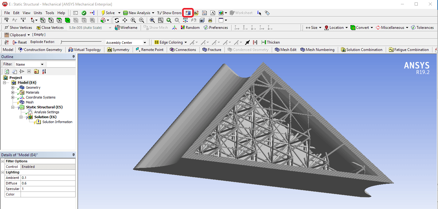
To mesh the lattice structure, I’ve found that inserting a Mesh Method and setting it to the Tetrahedrons/Patch Independent option has worked for getting a reasonable mesh. Care must be taken with element sizes or a very large mesh will be created. My example mesh has about 500,000 nodes. This is a section view, showing the mesh of the interior lattice structure (relatively coarse for the example).
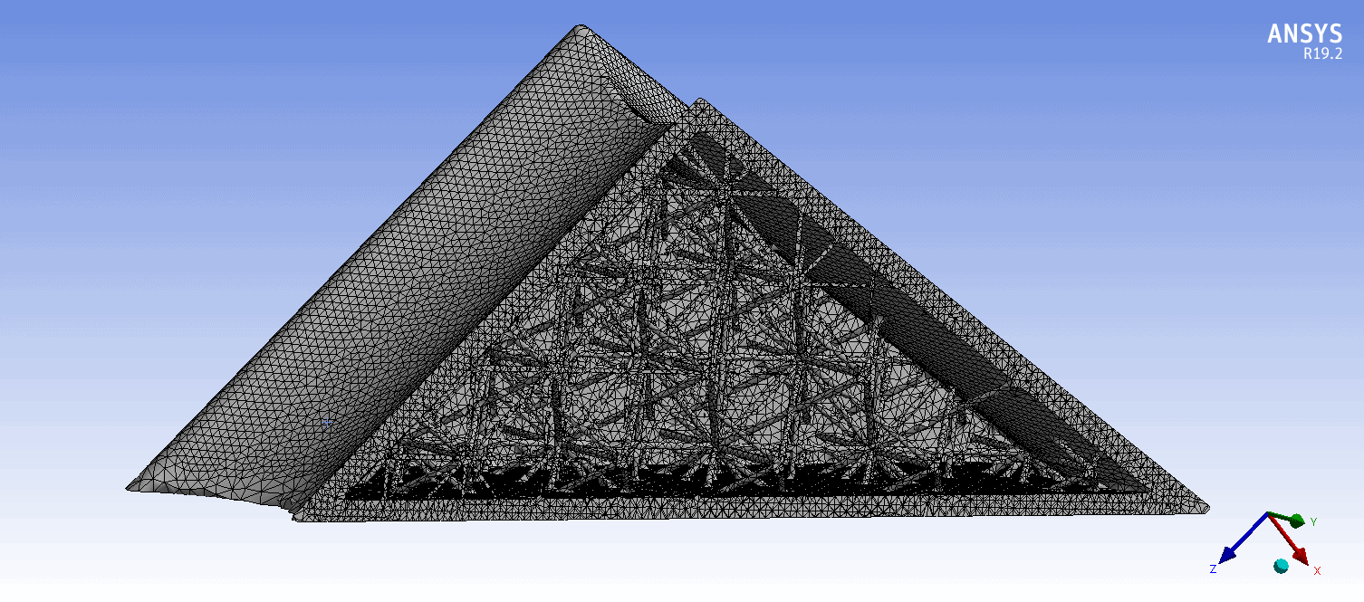
For boundary condition application, I used Direct FE loads. I used a lasso pick after aligned the view properly to select the nodes needed for the displacement and then the force loads, and created Named Selections for each of those nodal selections for easy load application.
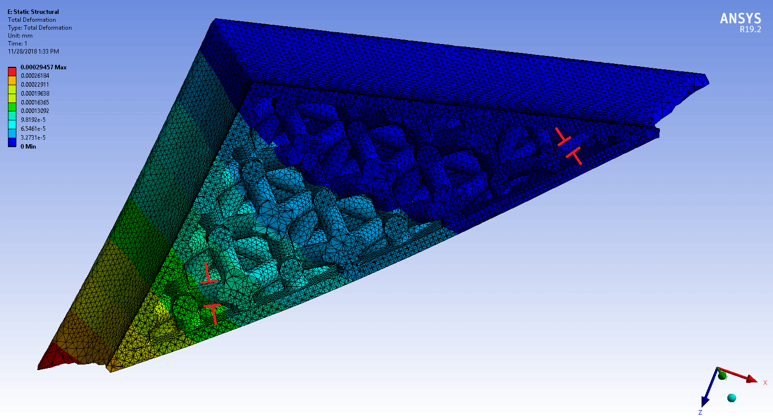
Here are a couple of results plots showing a section view with the lattice in the interior (deflection followed by max principal stress):
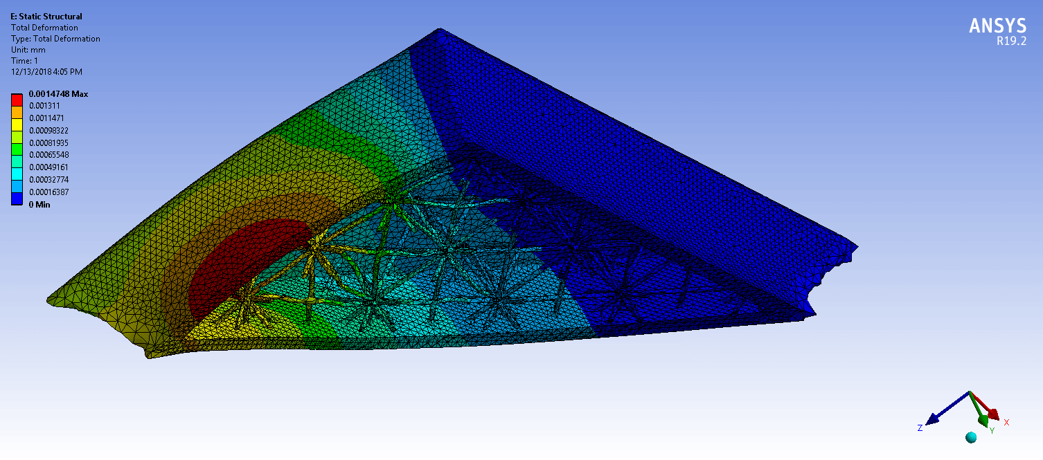
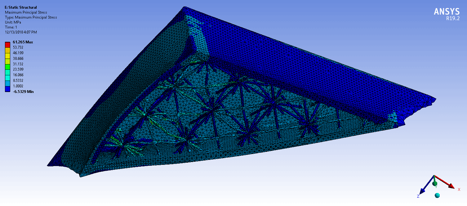
Here is a variant on the lattice specifications, in which the variance in the thickness of the lattice members (a result of the optimization) is more evident:
Clearly, a lot more could be done with the geometry in SpaceClaim before a validation step or 3D printing. However, hopefully this step by step guide is helpful with the basic process for performing a lattice optimization in ANSYS Mechanical and SpaceClaim 19.2.


