GrabCAD Print Software, Part Two: Simplify Set-ups, Save Time, and Do Cool Stuff You Hadn’t Even Considered

(Edited 3 August 2020 to reflect GrabCAD Print V1.44)

You haven’t really lived in the world of 3D printing until you’ve had a part fail spectacularly due to open faces, self-intersecting faces or inverted normals. Your part ends up looking more like modern art than technical part. Or perhaps the design you have in mind has great geometry but you wish that some parts could have regions that are dense and strong while other regions would work with minimal infill.

In Part One of this blog post about GrabCAD Print software, we covered the basics of setting up and printing a part; now we’ll look at several of the advanced features that save you set-up time and result in better parts.

Behind the Scenes Repairs

Stratasys GrabCAD Print software, available as a free download, is crafted for users setting up solid models for 3D printing on Stratasys FDM and PolyJet printers. Once you’ve started using it, you’ll find one of its many useful advanced features is the automated STL file-repair option.

MotorcycleWithErrorsRepairinGCP
Imported STL file, with GrabCAD Print ready to automatically repair errors. PADT image.

Most people still create solid models in CAD software then convert the file to the industry-standard STL format before opening it in a given 3D printer’s own set-up software. Every CAD package works a little differently to generate an STL file, and once in a while the geometry just doesn’t get perfectly meshed. Triangles may overlap, triangles may end up very long and very skinny, or the vector that signals “point in” or “point out” can get reversed.

Traditionally, the 3D printer set-up program reacts to these situations by doing one of two things: it prints exactly what you tell it to print (producing weird holes and shifted layers) or it simply refuses to print at all. Both situations are due to tiny errors in the conversion of a solid CAD model to a tessellated surface.

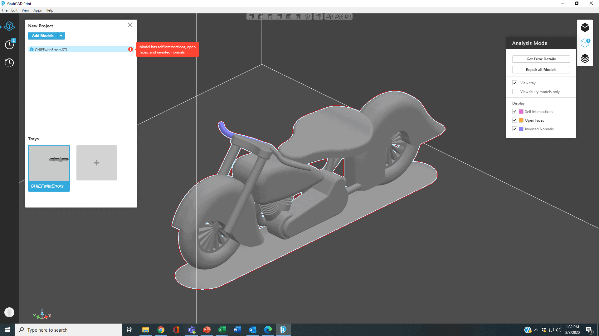
GrabCAD Print, however, gives your file a once-over and immediately flags sections of the model in need of repair. You can see a color-coded representation of all the problem areas, choose to view just some or all, and then click on Automatic Repair. No hand-editing, no counting layers and identifying sections where the problems reside – just a click of the virtual button and all the problem regions are identified, repaired and ready for the next processing steps.

CAD vs. STL: Do So Much More with CAD

GrabCAD Print also uniquely allows users to bring in their models in the original CAD file-format (from SolidWorks, Autodesk, PTC, Siemens, etc.) or neutral formats, with no need to first convert it to STL. For FDM users, this means GrabCAD recognizes actual CAD bodies, faces, and features, letting you make build-modifications directly in the print set-up stage that previously would have required layer-by-layer slice editing, or couldn’t have been done at all.

For example, with a little planning ahead, you can bring in a multi-body CAD model (i.e., an assembly), assemble and group the parts, then direct GrabCAD to apply different parameters to each body. This way you can reinforce some areas at full density then change the infill pattern, layout, and density in other regions where full strength is unnecessary.

Here’s an example of a SolidWorks model intended for printing with a solid lower base but lighter weight (saving material) in the upper sections. It’s a holder for Post-It® notes, comprising three individual parts – lower base, upper base and upper slot – combined and saved as an assembly.

Sample multi-body part ready to bring into GrabCAD Advanced FDM. Image PADT.

Sample multi-body part ready to bring into GrabCAD Advanced FDM. Image PADT.

Here was my workflow:

1 – I brought the SolidWorks assembly into GrabCAD, assembled and grouped all the bodies, selected an F370 Stratasys FDM printer, chose Print Settings of acrylonitrile butadiene styrene (ABS) and 0.010 inches layer height, and oriented the part.

2 -To ensure strength in the lower base, I selected just that section (you can do this either in the model tree or on the part itself) and opened the Model Settings menu at the right. Under Body, I chose Solid Infill.

3 – Next I selected the upper base, chose Hexagram, and changed the Infill Density to 60%.

4 – Lastly, I selected the upper slot section, chose Sparse, and changed the Infill Density to 35%.

5 – With all three sections defined, I clicked on Slice Preview, sliced the model and used the slider bar on the left to step through each section’s toolpath. For the screenshots, I turned off showing Support Material; the yellow bits indicate where seams start (another parameter that can be edited).

Here is each section highlighted, with screenshots of the parameter choices and how the part infill looks when sliced:

CombinedUpperBaseImages 1
Upper base set up in GrabCAD to print as Hexagram pattern, 60% infill; sliced toolpath shown at right. Image PADT.
CombinedUpperSlotImages
Upper slot section set up in GrabCAD to print as Sparse pattern, 35% infill; sliced toolpath shown at right. Image PADT.

So that you can really see the differences, I printed the part four times, stopping as the infill got partway through each section, then letting the final part print to completion. Here are the three partial sections, plus my final part:

PLAINholderthreesectionsLabeled
Lower base (solid), upper base (hexagram) and first part of upper slot (sparse), done as partial prints. Image PADT.
Completed note-holder set up in GrabCAD Print, Advanced FDM mode, weighted toward the bottom but light-weighted internally. Image PADT.
Completed note-holder set up in GrabCAD Print using advanced infill features, weighted toward the bottom but light-weighted internally. Image PADT.

Automated Hole Sizing Simplifies Adding Inserts

But like the old advertisements say, “But wait – there’s more!” Do you use heat-set inserts a lot to create secure connections between 3D printed parts and metal hardware? Planning ahead for the right hole size, especially if you have different design groups involved and fasteners may not yet be decided, this is the feature for you.

Sample part set up for easy insert additions, using Advanced FDM in GrabCAD Print. Image PADT.

Sample part set up for easy insert additions, using advanced, automated hole-resizing features in GrabCAD Print. Image PADT.

In your CAD part model, draw a hole that is centered where you know the insert will go, give it a nominal diameter and use Cut/Extrude so that the hole is at least the depth of your longest candidate insert. Save the file in regular CAD format, not STL. Next bring your part into GrabCAD Print and go to Model Settings in the right-hand menu.

This time, click on Face (not Body) and Select the inner cylindrical wall of your hole. Several options will become active, including Apply Insert. When you check that box, a new drop-down will appear, giving you the choice of adding a heat-set insert, a helicoil insert or creating a custom size. Below that you select either Inch or Metric, and for either, the appropriate list of standard insert sizes appears.

InsertAutoHoleResizing
Automatic hole-resizing in GrabCAD Print, for a specific, standard heat-set insert. Image PADT.

Choose the insert you want, click Update in the upper middle of the GrabCAD screen, and you’ll see the hole-size immediately changed (larger or smaller as needed). The new diameter will match the required oversized dimensions for the correct (melted into place) part-fit. You can even do this in a sidewall! (For tips on putting inserts into FDM parts, particularly with a soldering iron, see Adding Inserts to 3D Printed Parts: Hardware Tips.)

Note that this way, you can print the overall part with a sparse infill, yet reinforce the area around the insert to create just the right mass to make a solid connection. The Sliced view will show the extra contours added around each hole.

InsertSlicedView
Sliced view showing insert holes with reinforced walls, done in GrabCAD Print. Image PADT.
InsertManufNotes
Manufacturing notes automatically created in GrabCAD Print when insert holes are resized. Image PADT.

To document the selected choices for whoever will be doing the insert assembly, GrabCAD also generates a numbered, manufacturing-footnote that lists each insert’s size; this information can be exported as a PDF file that includes a separate close-up image of each insert’s location.

GrabCAD Print keeps adding very useful functions. Download it for free and try it out with template versions of the various Stratasys 3D printers, then email or call us to learn more.

PADT Inc. is a globally recognized provider of Numerical Simulation, Product Development and 3D Printing products and services. For more information on Stratasys printers and materials, contact us at info@padtinc.com.

Categories

Get Your Ansys Products & Support from the Engineers who Contribute to this Blog.

Technical Expertise to Enable your Addictive Manufacturing Success.

PADT Pulse Newsletter Screen Grab from March 2023

PADT’s Pulse Newsletter

Keep up to date on what is going on at PADT by subscribing to our newsletter.


By submitting this form, you are consenting to receive marketing emails from: . You can revoke your consent to receive emails at any time by using the SafeUnsubscribe® link, found at the bottom of every email. Emails are serviced by Constant Contact

Share this post:

Upcoming Events

05/31/2023

Driving Automotive Innovation with Additive - Webinar

05/24/2023

Hill Air Force Base Tech Expo

05/24/2023

Structural Updates in Ansys 2023 R1 (3) – Structural Optimization & Ex

05/23/2023

CROSSTALK 2023: Emerging Opportunities for Advanced Manufacturing Smal

05/10/2023

Signal & Power Integrity Updates in Ansys 2023 R1 - Webinar

04/26/2023

Additive Manufacturing Updates in Ansys 2023 R1 - Webinar

04/20/2023

38th Space Symposium Arizona Space Industry

More Info

04/19/2023

38th Space Symposium
Arizona Space Industry

04/19/2023

Additive Aids for Manufacturing - Webinar

04/18/2023

38th Space Symposium
Arizona Space Industry

04/17/2023

38th Space Symposium

04/13/2023

Venture Madness 2023

04/12/2023

Fluid Meshing & GPU-Solver Updates in Ansys 2023 R1 - Webinar

03/29/2023

8th Thermal and Fluids Engineering Conference

03/29/2023

Structural Updates in Ansys 2023 R1 - Composites, Fracture & MAPDL

03/28/2023

8th Thermal and Fluids Engineering Conference

03/27/2023

8th Thermal and Fluids Engineering Conference

03/26/2023

8TH Thermal and Fluids Engineering Conference

03/24/2023

Arizona BioPreneur Conference | Spring 2023

03/22/2023

2023 Arizona MedTech Conference

03/22/2023

Optimize Jigs & Fixtures with Additive - Webinar

03/15/2023

3D Design Updates in Ansys 2023 R1 - Webinar

03/08/2023

Competitive Advantages of 1D/3D Coupled Simulation - Webinar

03/01/2023

High Frequency Updates in Ansys 2023 R1 - Webinar

02/22/2023

Additive Advantages in Aerospace - Webinar

02/15/2023

Structural Updates in Ansys 2023 R1 (1) - Webinar

02/09/2023

IME 2023: MD&M | WestPack | ATX | D&M | Plastek

02/08/2023

IME 2023 MD&M | WestPack | ATX | D&M | Plastek

02/07/2023

IME 2023 MD&M | WestPack | ATX | D&M | Plastek

01/27/2023

Arizona Photonics Days, 2023

01/26/2023

Arizona Photonics Days, 2023

01/26/2023

TIPE 3D Printing | 2023

01/26/2023

Venture Cafe Phoenix Talent Night - Job Fari

01/26/2023

VFS 2023 Autonomous/Electric VTOL Symposium

01/25/2023

Arizona Photonics Days, 2023

01/25/2023

Building A.M.- Utah: Kickoff!

01/25/2023

TIPE 3D Printing | 2023

01/25/2023

VFS 2023 Autonomous/Electric VTOL Symposium

01/24/2023

VFS 2023 Autonomous/Electric VTOL Symposium

01/24/2023

TIPE 3D Printing | 2023

01/18/2023

2023 AZ Tech Council Golf Tournament

12/21/2022

Simulation Best Practices for 5G Technology - Webinar

12/14/2022

Digital Twins Updates in Ansys 2022 R2 - Webinar

12/08/2022

Tech the Halls - AZ Tech Council Holiday Mixer

12/07/2022

Electric Vehicle and Other Infrastructure Update Panel

11/30/2022

SPEOS Updates in Ansys 2022 R2 - Webinar

11/23/2022

Simulation Best Practices for Electronics Reliability - Webinar

11/16/2022

Discovery Updates in Ansys 2022 R2

11/10/2022

VentureCafe Phoenix Panel: Venture Capital in AZ

11/08/2022

2022 GOVERNOR’S CELEBRATION OF INNOVATION AWARDS + TECH SHOWCASE

11/03/2022

VentureCafe Phoenix Panel: Angel Investment in AZ

11/02/2022

High & Low Frequency Electromagnetics Updates in Ansys 2022 R2

10/26/2022

Simulation Best Practices For Chip-Package-System Design & Development

10/20/2022

Nerdtoberfest 2022

10/19/2022

2022 Southern Arizona Tech + Business Expo

10/19/2022

LS-DYNA Updates in Ansys 2022 R2 - Webinar

10/17/2022

Experience Stratasys Truck Tour - Clearfield Utah

10/14/2022

ASU School of Manufacturing Systems and Networks - Formal Opening Cele

10/14/2022

Experience Stratasys Truck Tour - Midvale Utah

10/12/2022

Experience Stratasys Truck Tour - Littleton Colorado

10/06/2022

Fluids Updates in Ansys 2022 R2 - Webinar

10/05/2022

Experience Stratasys Truck Tour - Colorado Springs

09/29/2022

White Hat Life Science Investor Conference - 2022

09/28/2022

2022 AZBio Awards

09/28/2022

Simulation Best Practices for Rotating Machinery Design & Development

09/21/2022

ExperienceIT NM 2022

09/21/2022

Additive Updates in Ansys 2022 R2 - Webinar

09/14/2022

Rocky Mountain Life Sciences Investor & Partnering Conference

09/08/2022

Ansys Optics Simulation User Group Meeting - Virtual

09/08/2022

Ansys Optics Simulation User Group Meeting

09/07/2022

SI & PI Updates in Ansys 2022 R2 - Webinar

08/31/2022

Simulation Best Practices for Developing Medical Devices - Webinar

08/24/2022

Mechanical Updates in Ansys 2022 R2 - Webinar

08/10/2022

Tucson after5 Tech Mixer: Ruda-Cardinal

08/05/2022

Flagstaff Tech Tour, 2022

08/02/2022

2022 CEO Leadership Retreat

08/01/2022

2022 CEO Leadership Retreat

07/27/2022

Thermal Integrity Updates in Ansys 2022 R1 - Webinar

07/20/2022

Simulation Best Practices for the Pharmaceutical Industry - Webinar

07/14/2022

NCMS Technology Showcase: Corpus Christi Army Depot

07/13/2022

NCMS Technology Showcase: Corpus Christi Army Depot

07/13/2022

Additive & Structural Optimization Updates in Ansys 2022 R1 - Webinar

07/07/2022

Arizona AADM Conference, 2022

06/29/2022

LS-DYNA Updates & Advancements in Ansys 2022 R1 - Webinar

06/23/2022

Simulation Best Practices for Wind Turbine Design - Webinar

06/15/2022

MAPDL Updates & Advancements in Ansys 2022 R1 - Webinar

06/01/2022

Mechanical Updates in Ansys 2022 R1 - pt. 2 Webinar

05/26/2022

Modelling liquid cryogenic rocket engines in Flownex - Webinar

05/25/2022

SMR & Advanced Reactor 2022

05/25/2022

05/24/2022

SMR & Advanced Reactor 2022

05/19/2022

RAPID + tct 2022

05/19/2022

Venture Cafe Roundtable: AI & Healthcare

05/18/2022

Tucson after5 Tech Mixer: World View

05/18/2022

RAPID + tct 2022

More Info

05/18/2022

Signal & Power Integrity Updates in Ansys 2022 R1 - Webinar

05/18/2022

Simulation World 2022

05/17/2022

RAPID + tct 2022

05/11/2022

Experience Stratasys Manufacturing Virtual Event

Search in PADT site

Contact Us

Most of our customers receive their support over the phone or via email. Customers who are close by can also set up a face-to-face appointment with one of our engineers.

For most locations, simply contact us: