
In Ansys Maxwell, windings can be added in Eddy Current and Transient Solvers. There are two types of conductors when assigning the windings: Solid and Stranded. What is the difference?
The Solid type considers the conductor as a solid part and therefore, the eddy current and AC effects will be taken into consideration. While the Stranded type assumes the conductor consists of infinite strands of tiny conductors and therefore, there is no eddy current inside the conductor.
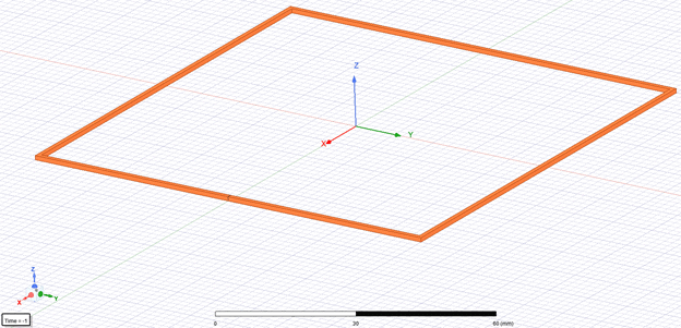
Now if there is no time-varying current or magnetic field in the model, will it be the same using Solid or Stranded? The answer is NO. Figure 1 shows a simple geometry of one-turn copper conductor. The cross-section is 1 mm by 1 mm and length of each edge is 100 mm. Assume the winding type is External and the circuit is shown below in Figure 2. The winding is connected to an external resistance (0.003 ohm) and the DC voltage source is 1 V.


The question will be: what is the current in the winding? Based on the physical geometry of the conductor, the conductor resistance can be calculated by R=ρ L/A, where L is the length of the conductor, A is the cross-sectional area and ρ is the resistivity of the copper material. The calculated conductor resistance is about 0.006872 ohm. The winding current will be different based on conductor type.
- Solid type
When the conductor is selected as Solid in ANSYS Maxwell, the winding resistance will be included while calculating the current. Therefore, the winding current will be:

Note: if the winding resistance is changing, the winding current will also change.
And the winding loss will be:

The winding loss calculated by Ansys Maxwell is 70.57 W which is identical to the result above.
- Stranded type
When the conductor is selected as Stranded in Ansys Maxwell, the winding resistance will NOT be included while calculating the current. Therefore, the winding current will be:

Note: the winding current is a constant no matter the winding resistance changes or not.
And the winding loss will be:

The winding loss calculated by Ansys Maxwell is 763.55 W which is identical to the result above.
Conclusion
- The Solid type is needed if the AC effect is of interest.
- For Voltage winding type, the DC winding current and DC winding loss will be different for Solid and Stranded types. If the load resistance is much larger/smaller than the winding resistance, this difference can be neglected.
- If the user is using the Voltage source and doing the EM-Thermal coupling simulation, it requires more attention as the temperature rise will increase the winding resistance and therefore, decrease the winding current (as the voltage is fixed). In this case, users can either choose Solid or add an additional scaling factor in the material property to compensate for the current difference.
If you would like more information related to this topic or have any questions, please reach out to us at info@padtinc.com.


